
Controllable flame stabilizer, engine and aircraft

A flame stabilizer and engine technology, applied in the direction of combustion method, indirect carbon dioxide emission reduction, combustion chamber, etc., can solve the problems of narrow engine flame stability boundary, repeated ignition, etc., to improve the stability of combustion boundary and work performance, and improve work performance , Improve the effect of filling ratio

Active Publication Date: 2021-09-24
NAT UNIV OF DEFENSE TECH
View PDF5 Cites 0 Cited by
  • Summary
  • Abstract
  • Description
  • Claims
  • Application Information

AI Technical Summary

Problems solved by technology

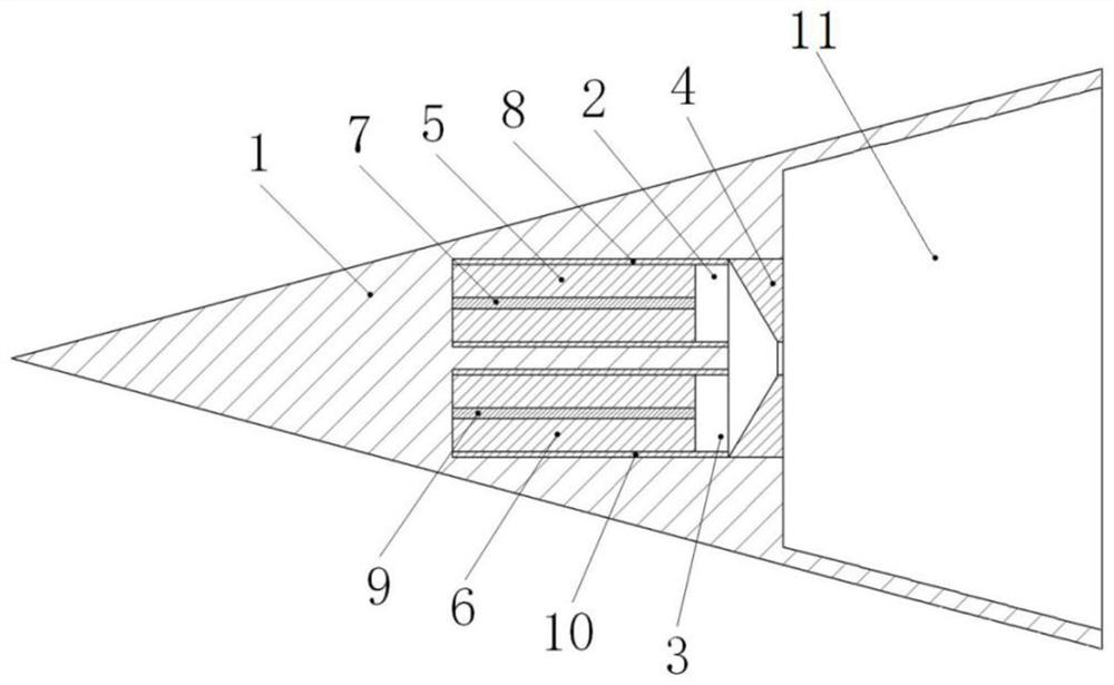
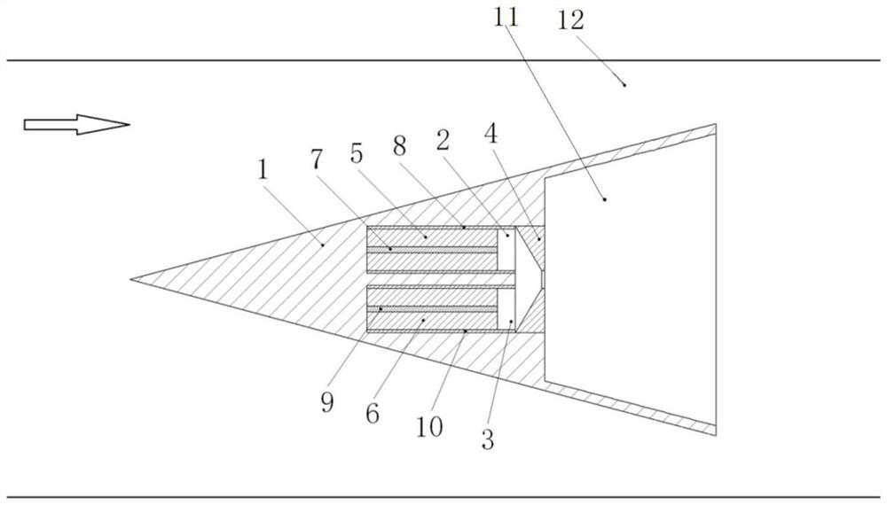
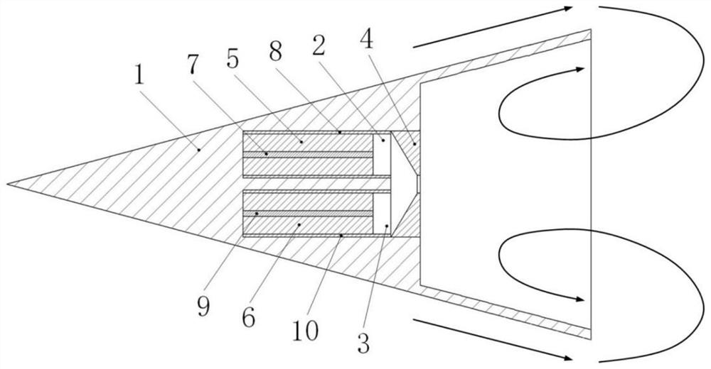
[0007] Aiming at the defects existing in the prior art, the present invention provides a controllable flame stabilizer, engine and aircraft, which helps to solve the problems of narrow engine flame stability boundary and repeated ignition at the same time

Method used


Image

  • Controllable flame stabilizer, engine and aircraft
  • Controllable flame stabilizer, engine and aircraft
  • Controllable flame stabilizer, engine and aircraft

Examples


Embodiment Construction

[0037] The following will clearly and completely describe the technical solutions in the embodiments of the present invention with reference to the accompanying drawings in the embodiments of the present invention. Obviously, the described embodiments are only part of the embodiments of the present invention, not all of them. Based on the embodiments of the present invention, all other embodiments obtained by persons of ordinary skill in the art without creative efforts fall within the protection scope of the present invention.

[0038] It should be noted that all directional indications (such as up, down, left, right, front, back...) in the embodiments of the present invention are only used to explain the relationship between the components in a certain posture (as shown in the accompanying drawings). Relative positional relationship, movement conditions, etc., if the specific posture changes, the directional indication will also change accordingly.

[0039] In addition, in t...


PUM


Abstract

The invention discloses a controllable flame stabilizer, an engine and an aircraft. The controllable flame stabilizer is installed in an engine combustion chamber and comprises a shell, an electric control fuel gas generator and a spray pipe are arranged in the shell, and the electric control fuel gas generator comprises a fuel-rich electric control solid propellant combustion chamber and an oxygen-rich electric control solid propellant combustion chamber; one end of the fuel-rich electronic control solid propellant combustion chamber and one end of the oxygen-rich electronic control solid propellant combustion chamber are respectively a fuel-rich storage cavity used for containing a fuel-rich electronic control solid propellant and an oxygen-rich electronic control solid propellant storage cavity used for containing an oxygen-rich electronic control solid propellant; and independently-controlled electric ignition mechanisms are respectively arranged in the fuel-rich electric control solid propellant combustion chamber and the oxygen-rich electric control solid propellant combustion chamber. The fuel-rich propellant and the oxygen-rich propellant can be ignited and combusted separately or simultaneously according to the flight working condition and the maneuvering requirement of the engine, so that the air-fuel ratio is kept in a better state, and the stable combustion boundary and the engine performance are improved.

Description

technical field [0001] The invention relates to the technical field of engines, in particular to a controllable flame stabilizer, an engine and an aircraft. Background technique [0002] Flame stabilizers are an important component of aero turbine engines and ramjet engines. In an aero turbine engine or a ramjet engine, due to the high speed of the incoming air, it is quite difficult to fully mix the fuel with the incoming air, to ignite and to burn stably, and even flameout occurs during the flight. In order to improve the combustion efficiency of the fuel in the combustion chamber of the ramjet engine and prevent the flame from quenching, a flame stabilizer is often installed in the combustion chamber in practical applications. The incoming air enters the combustion chamber through the intake port. In the combustion chamber, the high-speed incoming air reacts with gas or fuel, and the high-speed gas generated is ejected from the nozzle to generate thrust. [0003] In add...

Claims


Application Information

Patent Timeline
IPC IPC(8): F23R3/28
CPCF23R3/28Y02E20/34
Inventor 段炼陈斌斌夏智勋李洋马立坤冯运超何志成
Owner NAT UNIV OF DEFENSE TECH
Learn More