
Water area floating aeration device

A technology for aeration devices and water areas, applied in biological treatment devices, biological water/sewage treatment, water/sludge/sewage treatment, etc., can solve problems such as immersion, failure to aerate water areas smoothly, internal equipment damage, etc., to achieve It is convenient for transportation and adjustment, improves the scope and convenience of use, and prolongs the effect of contact time

Active Publication Date: 2021-09-24
宁波碧城生态科技有限公司
View PDF4 Cites 1 Cited by
  • Summary
  • Abstract
  • Description
  • Claims
  • Application Information

AI Technical Summary

Problems solved by technology

[0005] Aiming at the deficiencies of the prior art, the present invention provides a water area floating aeration device, which solves the problem that the existing water area floating aeration device is submerged in the water area due to insufficient length during use, and cannot perform water area aeration smoothly. operation, and the long-term injection of water flow is likely to cause damage to internal equipment

Method used


Image

  • Water area floating aeration device
  • Water area floating aeration device
  • Water area floating aeration device

Examples


Embodiment 1

[0044] See Figure 1-6 The present invention provides a technical solution: A water floating aerator comprises:

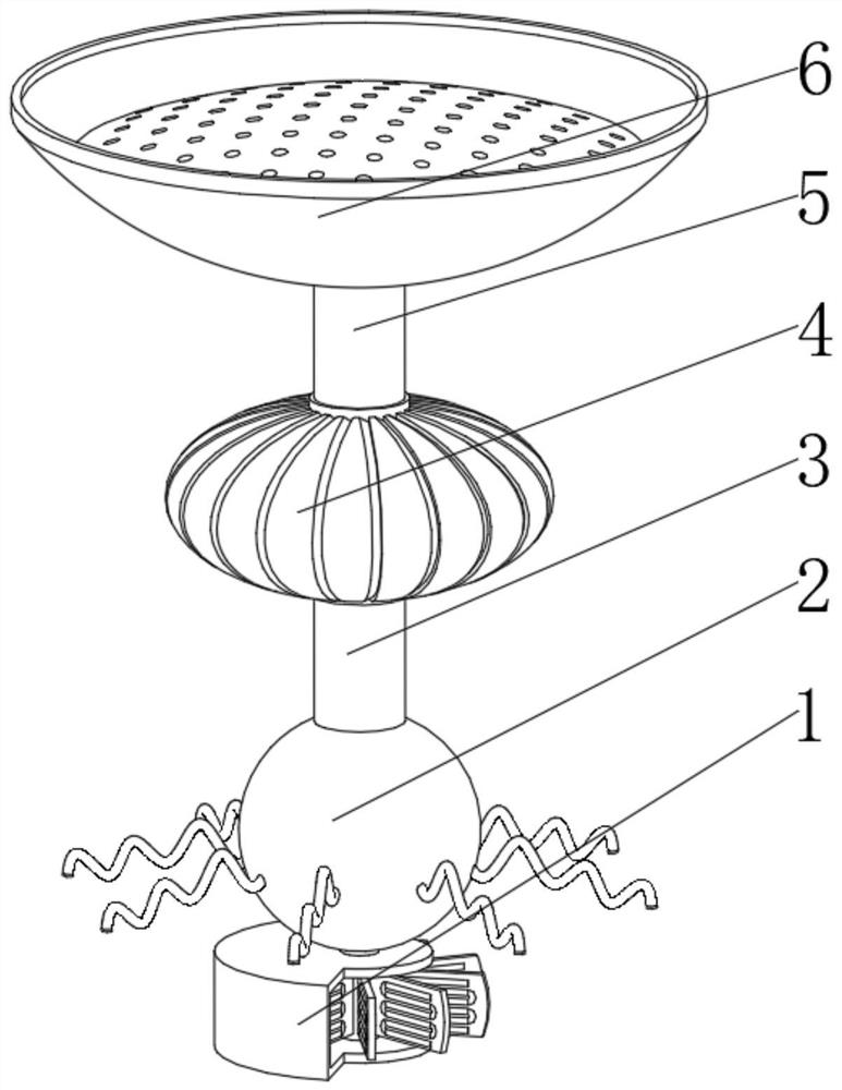
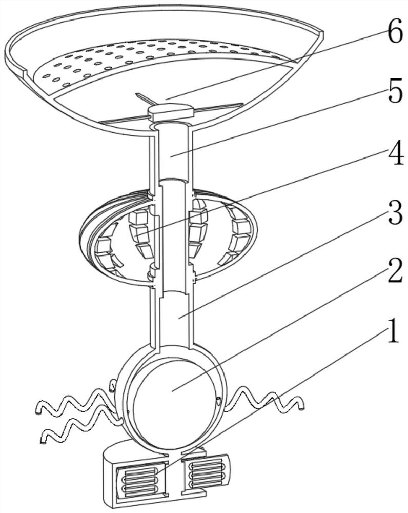
[0045] Water apparatus 1, the flow device 1 has a columnar main body, and air supply means mounted on the top of the columnar body 2, and mounted at 3, and a flotation device transmits air bar at the top of the air supply means 2 mounted on top of the transport air bar 3, 4, and 6, an air intake pipe means 5 is mounted on the top of the flotation device 4, and an intake device 5 is mounted on top of the intake pipe 2 comprises:

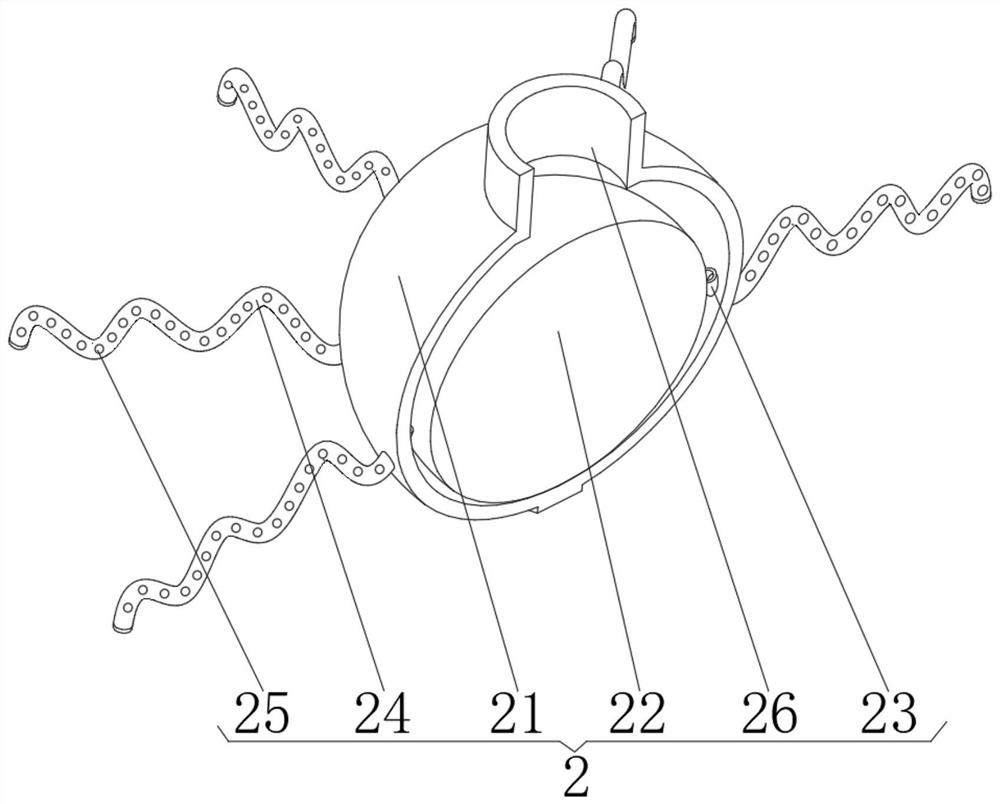
[0046] Ventilation spherical shell 21, the breather housing having a spherical ball socket 21, and the counterweight mounted on the bottom of the ball of the spherical housing interior 22, and through holes at the position of the spherical surface of the outer housing 23 defines, in the through hole 23 and the mounting the inner surface of the outlet hose 24, and opening 25, and the spherical top of the housing defines an intermediate position ...

Embodiment 2

[0058] See Figure 1-6 , Based on the first embodiment, the present invention provides a technical solution: A method of using the water floating aerator: Step 1: The quality and size of the counterweight ball 22 is adjusted, and the rotation into the intake pipe 5 such that 5 the inner pipe coils vertical adjustment surface 41, after which it was sunk in the water:

[0059] Step two: buoyancy ellipsoidal mask plate 43 and the ball 61 such that the top of the device generated in the water;

[0060] Step three: the flow of water will drive the flow plate 14 and the ellipsoidal plate 43 is rotated, so that the effect of the wire 15 is rotated and the respective magnetically block 45, respectively, and the magnetic disk 12 and the induction coil 41 in the inner coils with each other electromagnetic conversion, for energizing the device;

[0061] Step Four: Energy power through column 13, the transmission lever air intake pipe 3 and 5 energy transmission, energy is supplied to the air ...


PUM


Abstract

The invention discloses a water area floating aeration device which specifically comprises a water flow device, an air supply device installed on the top of a columnar main body, a floating device installed on the top of a transmission air rod and an air inlet device installed on the top of an air inlet pipe, wherein the air supply device comprises a ventilation ball shell, a counterweight ball mounted at the bottom of an inner cavity of the spherical shell, a through hole formed in the lower middle position of the outer surface of the spherical shell, an air outlet hose mounted on the inner surface of the through hole, and bubble holes formed in the front face and the back face of the air outlet hose. The invention relates to the technical field of environmental protection. Through arrangement of the counterweight ball and mutual cooperation of the counterweight ball and the floating device, the depth of the whole equipment in a water area is adjusted, the bottom of the equipment is ensured to be in contact with water flow at the bottom of the water area while the whole equipment is prevented from being immersed, aeration work can be smoothly carried out, and meanwhile, the wave-shaped air outlet hose is used for resisting foreign objects and protecting the equipment.

Description

Technical field [0001] The present invention relates to the field of environmental protection, in particular to a water floating aerator. Background technique [0002] Due to the different major pollution of water, repair methods are also different. When the main pollutants of organic pollution, pollution by controlling the dissolved oxygen, pollutants in the river fishing clear, by the method of aeration oxygen in the air into the water so that the water aerobic bacteria, growth and reproduction of aquatic organisms, and gradually establish water the food chain, and then assisted the river dredging, flocculant dosing, methods of growing aquatic plants affected by the contaminated water be completely repaired. [0003] Floating aerator conventional water during use, due to insufficient length itself is immersed in water, the aerated water can not operate smoothly, while long poured into water easily cause internal damage to the device. Inventive content [0004] (1) Solving tech...

Claims


Application Information

Patent Timeline
Patent Type & Authority Applications(China)
IPC IPC(8): C02F3/02B01D46/10
CPCC02F3/02B01D46/103C02F2203/006Y02W10/10
Inventor 程春龙
Owner 宁波碧城生态科技有限公司
Learn More