
Variable open winding motor topology driving circuit and control method thereof

A technology of a driving circuit and a control method, which is applied in the field of variable open-winding motor topology driving circuit and its control, can solve the problems of large switching loss and low utilization rate of DC voltage, etc.

Active Publication Date: 2021-09-21
BEIJING INSTITUTE OF TECHNOLOGYGY
View PDF10 Cites 1 Cited by
  • Summary
  • Abstract
  • Description
  • Claims
  • Application Information

AI Technical Summary

Problems solved by technology

[0004] In the existing technology, the traditional three-phase inverter drive control structure or the open-winding motor drive structure of the common DC bus are commonly used. However, for these two drive circuits, their use has limitations in response to different changes in the working conditions of the motor. , which leads to the disadvantages of large switching loss and low DC voltage utilization

Method used


Image

  • Variable open winding motor topology driving circuit and control method thereof
  • Variable open winding motor topology driving circuit and control method thereof
  • Variable open winding motor topology driving circuit and control method thereof

Examples


Embodiment 1

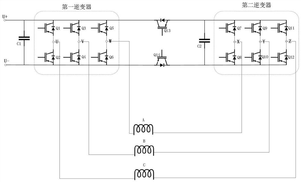
[0018] as attached figure 1 As shown, it is a schematic diagram of a variable open-winding motor driving topology of a variable open-winding motor topology driving circuit of this embodiment.

[0019] This embodiment provides a variable open-winding motor topology drive circuit, including a first inverter and a second inverter, and a switch is provided at the DC bus between the first inverter and the second inverter tube, by controlling the on and off of the switch tube, the function switching between the three-phase inverter drive control circuit and the open-winding motor drive circuit of the common DC bus is realized.

[0020] The first inverter includes three sets of switching tubes Q1, Q2, Q3, Q4, Q5, and Q6 connected in parallel, and the second inverter includes three sets of switching tubes Q7, Q8, Q9, Q10, and Q11 connected in parallel. , Q12, switch tubes Q13 and Q14 are set at the DC bus between the first inverter and the second inverter, one side of the first inver...

Embodiment 2

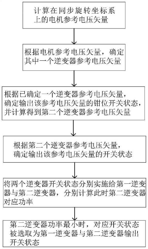
[0030] This embodiment provides a control method for a variable open-winding motor topology drive circuit, and the specific implementation is as follows:

[0031] The control process of the variable open-winding motor topology drive circuit in this embodiment is mainly divided into the following working conditions:

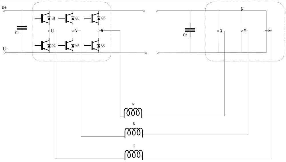
[0032] 1. As attached image 3 As shown, when the motor speed is lower than 30% of the rated speed, the back electromotive force of the permanent magnet synchronous motor is low. Compared with the common bus open-winding drive structure, the traditional three-phase inverter structure can be satisfied by using fewer switching tubes and switching times. Motor operating conditions. At this time, the DC bus of the first inverter is connected to the DC source, the two switching tubes Q13 and Q14 at the common DC bus are disconnected, and the switching tubes of the second inverter are all turned on. At this time, the bridge arms of the first inverter form a traditiona...


PUM


Abstract

The invention relates to the technical field of motor driving circuits, and particularly relates to a variable open winding motor topology driving circuit and a control method thereof. The driving circuit comprises a first inverter and a second inverter, a switching tube is arranged at a direct current bus between the first inverter and the second inverter, and function switching of the three-phase inverter driving control circuit and the open winding motor driving circuit sharing the direct current bus is realized by controlling on and off of the switching tube. According to the variable open winding motor topology driving circuit and the control method thereof, the driving circuit of a topology structure is provided, and the requirements of minimum switching loss and improvement of the direct current voltage utilization rate in different states can be met according to the working condition of the motor in cooperation with different control strategies.

Description

technical field [0001] The invention relates to the technical field of motor drive circuits, in particular to a variable open-winding motor topology drive circuit and a control method thereof. Background technique [0002] The common DC bus is mainly used in the multi-motor transmission system to control the high precision of the speed control system, and at the same time to rationally utilize and recover the regenerative energy generated by the system during the braking process. [0003] The public DC bus adopts a separate rectification / feedback device to provide a certain power DC source for the system, and the inverter for speed regulation is directly connected to the DC bus. When the system works in the electric state, the inverter obtains electric energy from the busbar; when the system works in the power generation state, the energy is directly fed back to the grid through the busbar and the feedback device, so as to achieve energy saving, improve equipment operation r...

Claims


Application Information

Patent Timeline
IPC IPC(8): H02P25/02H02P25/16H02P21/00
CPCH02P25/02H02P25/16H02P21/0003
Inventor 宋强孙芃李易庭田从丰张圆圆张如伟刘存波
Owner BEIJING INSTITUTE OF TECHNOLOGYGY
Learn More