
Direct-current circuit breaker and application method thereof

A technology of DC circuit breaker and application method, which is applied in the direction of DC network circuit devices, circuits, circuit devices, etc., can solve the problems that mechanical switches cannot be reliably extinguished and turned off, achieve high withstand voltage, increase oscillation frequency, and shorten oscillation the effect of time

Pending Publication Date: 2021-09-21
GLOBAL ENERGY INTERCONNECTION RES INST CO LTD +1
View PDF5 Cites 3 Cited by
  • Summary
  • Abstract
  • Description
  • Claims
  • Application Information

AI Technical Summary

Problems solved by technology

[0003] Therefore, the technical problem to be solved by the present invention is to overcome the defect that the mechanical switch in the DC circuit breaker in the prior art cannot be reliably extinguished and turned off, thereby providing a DC circuit breaker and its application method

Method used


Image

  • Direct-current circuit breaker and application method thereof
  • Direct-current circuit breaker and application method thereof
  • Direct-current circuit breaker and application method thereof

Examples


Embodiment 1

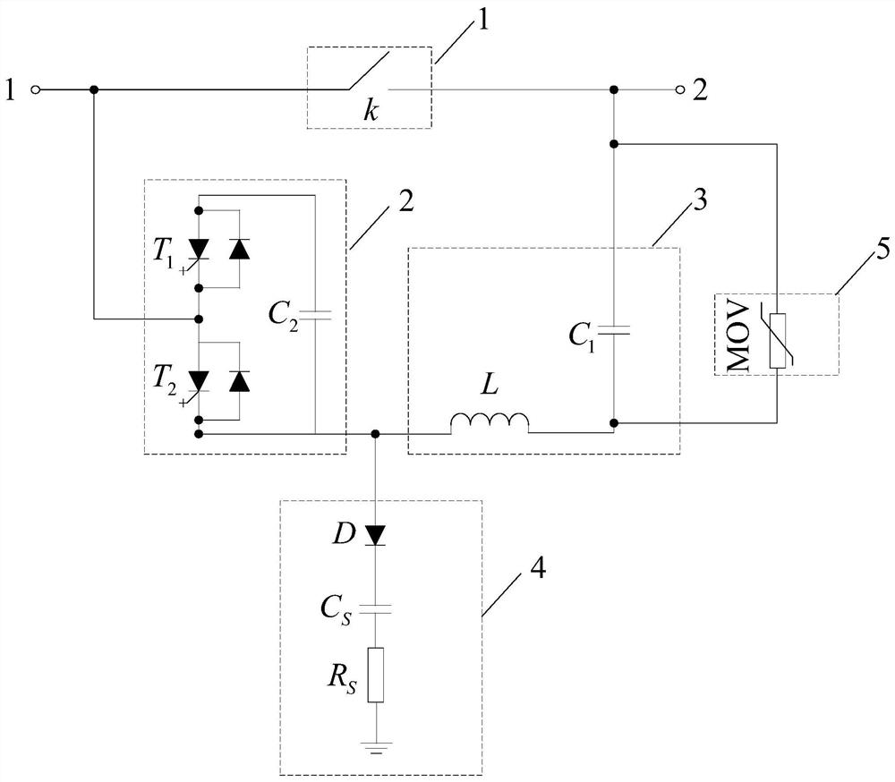
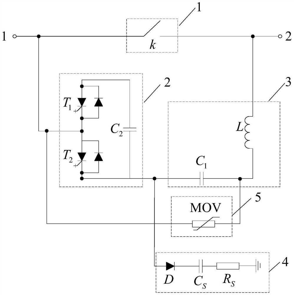
[0031] Embodiment of the present invention provides a DC circuit breaker, it can be applied to HVDC system applications, such as Figure 1 (a) ~ 1 (c) Shown, comprising: a branch flow, the controlled power supply unit 2, the oscillating arm 3, ground units 4 and 5 energy branch.

[0032] like Figure 1 (a) ~ 1 (c) , The flow branches to an embodiment of the present invention in series with the power line, comprising at least one branch flow high-speed mechanical switch; a first end and a first end of the branch flow controlled power supply unit is connected, controlled a second terminal respectively connected to a first end of the power supply unit, a first end of the grounding unit oscillating branch; branch connected to a second end of the oscillating end of the second branch flow; a second terminal of the grounding unit.

[0033] Specifically, such as Figure 1 (a) ~ 1 (c) , The branch for the LC oscillator oscillating arm, comprising an oscillator capacitor C 1 And an oscillation...

Embodiment 2

[0042] Application of the method of the present invention provides a DC breaker, dc circuit breaker based on embodiment 1, as figure 2 , An application method comprising:

[0043] Step S11: real-time monitoring of power lines at both ends of the branch flow connection malfunctions.

[0044] Step S12: When the flow branch power line connected to at least one end of the short-circuit failure occurs, the power supply unit controlled by the control flow and operational state of the branch, the oscillating arm short-circuit fault current magnitude equal and opposite oscillating current, such that the flow branches off reliably.

[0045] Specifically, as shown in FIG. 1, when the power lines # 1, # 2, no power line failure occurs, the branch flow in the conduction state, the realization of power lines and power lines # 1 # 2 between DC loading transmitting current, and the DC system is oscillating arm, the controlled pre-charge power source unit, the oscillating arm can be self-created;...


PUM


Abstract

The invention discloses a direct-current circuit breaker and an application method thereof. The direct-current circuit breaker is characterized in that a through-current branch circuit is connected in series into a power line; a controlled power supply unit is connected with the through-current branch circuit, an oscillation branch circuit and a grounding unit; and an energy consumption branch circuit can be connected with the main through-flow branch circuit in parallel and can also be connected with the oscillation branch circuit. When the power line does not have a fault, the through-flow branch circuit conducts a direct-current load current, a direct-current system pre-charges the oscillation branch circuit and the controlled power supply unit, and the oscillation branch circuit realizes self-energy taking; and when a short-circuit fault occurs in the power line, the oscillation branch circuit generates an oscillation current which is equal to a fault current in amplitude and opposite to the fault current in direction by controlling the operation states of the controlled power supply unit and the through-flow branch circuit, so that the through-flow branch circuit is reliably turned off, the amplitude of an injection current is improved by adopting a controlled active oscillation boosting principle, and arc extinguishing on-off of the through-current branch circuit is realized.

Description

Technical field [0001] The present invention relates to the field of power electronics technology, particularly to a DC circuit breaker and application method. Background technique [0002] DC transmission and distribution system failures rapid development, fast growth in current and reliable fault isolation is the key to its safe and stable operation of the guarantee. DC circuit breaker is a high-tech economy of the DC transmission and distribution system to support the development and application of core equipment. Currently, the widely used mainly in high-voltage DC circuit breaker there are two types of mechanical DC breaker, arc-quenching to achieve a mechanical switch off the reverse current is injected through a single, low loss, but there is a long time reclosing, small current breaking renewed risk of mechanical switches, the breaking process and easily form an oscillation of the DC system, poses a potential threat to the safe operation of the system and other normal equ...

Claims


Application Information

Patent Timeline
Patent Type & Authority Applications(China)
IPC IPC(8): H02H7/26H02J1/00H01H9/54
CPCH02H7/268H02J1/00H01H9/54
Inventor 张升刘远贺之渊周万迪高冲李弸智
Owner GLOBAL ENERGY INTERCONNECTION RES INST CO LTD
Learn More