Method, device and equipment for calculating lightning induced voltage of insulated joint and medium
An insulating joint and lightning induction technology, which is applied in computer-aided design, calculation, design optimization/simulation, etc., can solve the problem that the electrical connection of pipelines on both sides cannot be isolated, the frequency variation characteristics of soil resistivity are not considered, and the actual situation varies greatly. and other problems, to achieve the effect of flexible path planning, saving manpower and material resources, and convenient operation.
- Summary
- Abstract
- Description
- Claims
- Application Information
AI Technical Summary
Problems solved by technology
Method used
Image
Examples
Embodiment 1
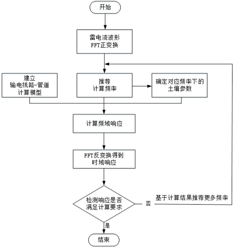
[0039] refer to figure 1 , a method for calculating lightning-induced voltage at insulating joints of buried pipelines, comprising the following steps:
[0040] Step 1. Collect transmission line parameters and oil and gas pipeline parameters. The transmission line information includes the line span, the height of the overhead line, the structure of the tower and the structure of the grounding device, etc. Oil and gas pipeline parameters include pipeline size, oil and gas pipeline burial depth, anti-corrosion layer parameters, and the location of insulating joints. In addition, it is also necessary to collect the spatial relative positions of oil and gas pipelines and transmission lines, as well as the local power frequency soil resistivity.
[0041] Step 2. Based on the electric line parameters collected in step 1, the oil and gas pipeline parameters, the spatial relative position of the oil and gas pipeline and the transmission line, and the local power frequency soil resisti...
Embodiment 2
[0055] A calculation method for lightning induced voltage of an insulating joint, comprising the following steps:
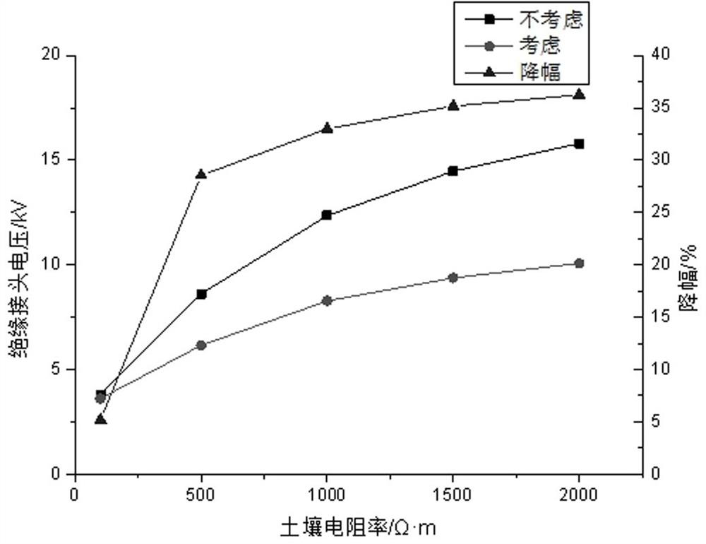
[0056] Step 1, line parameters: tower height 85m, line span 500m, ground wire diameter 1.66cm, grounding device is a square frame with ray structure, the side length of the box is 15m, the ray length is 20m, and the grounding conductor is a steel conductor with a radius of 1cm. Pipeline parameters: the buried depth is 1.5m, the length is 50km, the diameter is 406mm, the wall thickness is 6mm, and the surface resistivity of the anti-corrosion layer is 10 5 Ω·m 2 , The thickness of the anti-corrosion layer is 3mm. The pipeline is parallel to the transmission line with a distance of 30m, and the insulating joint of the pipeline is located at the nearest position to the tower struck by lightning. The soil resistivity is 1000Ω·m.
[0057] Step 2, establish a frequency domain calculation model according to the above parameters;
[0058] Step 3, the lightning curren...
Embodiment 3
[0065] Such as image 3 As shown, a lightning induced voltage calculation device for insulating joints provided by the present invention includes an acquisition module and a calculation output module;
[0066] Among them, the collection module is used to collect data, and transmit the collected data to the calculation output module; the data includes electric line parameters, oil and gas pipeline parameters, spatial relative positions of oil and gas pipelines and transmission lines, and local soil resistivity.
[0067] The calculation output module is used to collect the data collected by the module, establish the frequency domain calculation model of the interference voltage of the transmission line to the nearby pipeline, and then calculate the lightning induced voltage of the buried pipeline insulation joint by the frequency domain calculation model of the nearby pipeline interference voltage.
PUM
 Abstract
Description
Claims
Application Information
 - R&D
- Intellectual Property
- Life Sciences
- Materials
- Tech Scout
- Unparalleled Data Quality
- Higher Quality Content
- 60% Fewer Hallucinations
Browse by: Latest US Patents, China's latest patents, Technical Efficacy Thesaurus, Application Domain, Technology Topic, Popular Technical Reports.
© 2025 PatSnap. All rights reserved.Legal|Privacy policy|Modern Slavery Act Transparency Statement|Sitemap|About US| Contact US: help@patsnap.com


