A winding coating machine

A coating machine and coating chamber technology, applied in the field of winding vacuum coating, can solve the problems of the influence of flexible film winding coating, unfavorable high-efficiency production scheduling plan, low work efficiency, etc., so as to improve the continuity of production links and production efficiency, Save the non-coating work process cycle, realize the effect of automation and intelligence

Active Publication Date: 2022-06-21
泊肃叶科技(沈阳)有限公司
View PDF0 Cites 0 Cited by
  • Summary
  • Abstract
  • Description
  • Claims
  • Application Information

AI Technical Summary

Problems solved by technology

At present, the weight of the coils of flexible film products produced by some mainstream manufacturers has even reached the order of several tons per roll. This weight makes the loading and unloading of coils during coil replacement time-consuming and labor-intensive, requiring a lot of labor to complete. , especially when the number of coil coating equipment working at the same time increases, the heavy coil loading and unloading work brings great troubles to production scheduling, which is not conducive to the implementation of efficient production scheduling plans
[0003] On the other hand, the current large-scale roll-to-roll coating equipment generally has the problem of low automation, and requires more manual participation to complete tedious production peripheral tasks such as coil loading and unloading, film penetration, and coating material replacement. Resulting in lower work efficiency and higher failure rate, which has a serious impact on the smooth production process of flexible film winding coating
[0004] The above status is obviously not in line with the development concept of highly automated intelligent manufacturing and intelligent factories in the current industrial trend

Method used


Image

  • A winding coating machine
  • A winding coating machine

Examples


Embodiment Construction

[0030] Embodiments of the present invention are further described below with reference to the accompanying drawings. It should be understood that the specific embodiments described herein are only used to illustrate and explain the present invention, but not to limit the present invention.

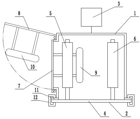
[0031] figure 1 It is a top-view structural schematic diagram of an embodiment of the winding coating machine of the present invention. As shown in the figure, a winding coating machine of the present invention mainly includes a coating chamber 1 , a mobile winding system unit 2 and a vacuum system 3 ; The mobile winding system unit 2 is sealed with the coating chamber 1 to form a vacuum chamber; the mobile winding system unit 2 includes a wall plate 4 and a winding system arranged on the wall plate, and the winding system includes a winding roller 5 and unwinding roller 6. The coil coating machine also includes a coating chamber door 7 and a coating chamber door 8, and the two coating c...


PUM


Abstract

The invention discloses a winding coating machine, which mainly includes a coating chamber, a movable winding system unit, a coating chamber door, an evaporation source and a vacuum system; the movable winding system unit is sealed and docked with the coating chamber to form a vacuum chamber ;The mobile winding system unit includes a wallboard and a winding system set on the wallboard. The winding system includes a winding roller and an unwinding roller; the mobile winding system unit and the winding system can be loaded, unloaded and replaced by moving as a whole , the loading, unloading and replacement actions are automatically completed by the loading and unloading device; there are two loading and unloading devices, which are respectively set on the mobile trolley 1 and the mobile trolley 2, and the mobile trolley 1 and the mobile trolley 2 can be laid along the winding coating machine track moves. Before the loading, unloading and replacement action starts, in the new mobile winding system unit loaded on the mobile trolley 2, the unwinding roller has been replaced with a new flexible film roll, and the flexible film has been completed on the winding system. Through the film.

Description

technical field [0001] The invention belongs to the technical field of winding vacuum coating, in particular to a winding coating machine. Background technique [0002] With the increasingly widespread application of roll-to-roll vacuum coating technology in emerging fields such as new energy power batteries, the size and weight of coils used in roll-to-roll coating machines are also gradually expanding. At present, the weight of the flexible film product rolls produced by some mainstream manufacturers even reaches the order of several tons per roll. This weight makes the loading and unloading of the rolls time-consuming and laborious, and requires a lot of labor to complete. , especially when the number of coiled coating equipment working at the same time increases, the heavy coil loading and unloading work brings great trouble to the production scheduling and is not conducive to the implementation of efficient production scheduling. [0003] On the other hand, the current...

Claims


Application Information

Patent Timeline
Patent Type & Authority Patents(China)
IPC IPC(8): C23C14/56C23C14/54C23C14/24
CPCC23C14/562C23C14/54C23C14/24
Inventor 李成林杜雪峰郝明
Owner 泊肃叶科技(沈阳)有限公司
Why Eureka
Try Eureka