Image fusion device based on optical coherence elastography
A technology of elastography and image fusion, which is applied in the fields of medical science, diagnosis and diagnosis using light, which can solve the problems of troublesome and laborious switching, and achieve the effect of simple operation.
- Summary
- Abstract
- Description
- Claims
- Application Information
AI Technical Summary
Problems solved by technology
Method used
Image

Examples
Embodiment 1
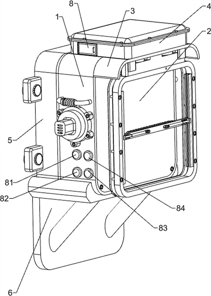
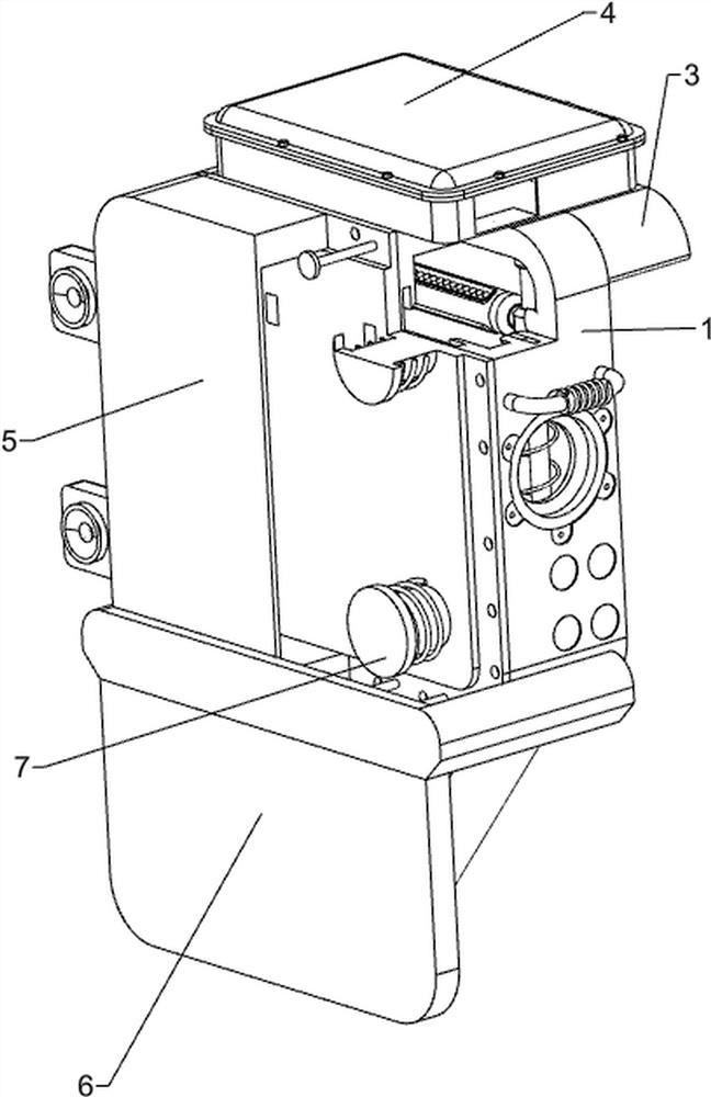
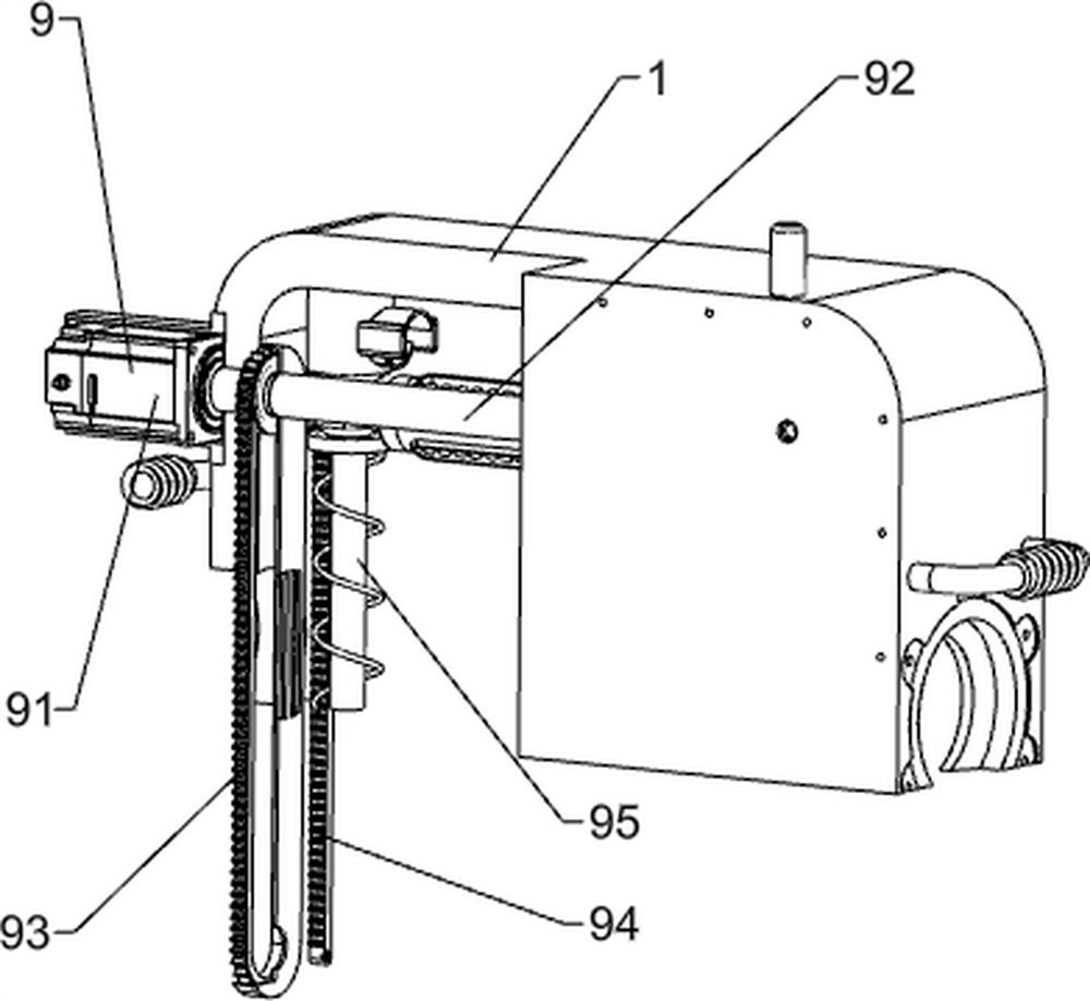
[0038] An image fusion device based on optical coherence elastography, such as Figure 1-Figure 7As shown, it includes a heat dissipation box 1, a light-transmitting film 2, a light-shielding top plate 3, a fixed top box 4, a fixed frame 5, a supporting bottom plate 6, a hydraulic column 7, a raise button 81, a lower button 82, a light button 83, and a switch The button 84, the image detection mechanism 9 and the switch mechanism 10, the heat dissipation box 1 is slidingly arranged in the fixed frame 5, the front part of the heat dissipation box 1 is provided with a light-transmitting film 2, and the upper front side of the heat dissipation box 1 is provided with a light-shielding top plate 3 A fixed top box 4 is arranged between the outer top of the heat dissipation box 1 and the outer top of the shading top plate 3, the bottom of the fixed frame 5 is fixedly connected with a support base plate 6, and the inner left side of the fixed frame 5 is provided with a hydraulic column...
Embodiment 2
[0043] On the basis of Example 1, such as Figure 8-Figure 14 As shown, a clamping mechanism 11 is also included, and the clamping mechanism 11 includes a geared motor 111, a driving worm 112, a driven worm wheel 113, a synchronous belt assembly 114, a vertical shaft 115, a column disc 116, a buffer guide rail 117, Positioning block 118, clamping frame 119, buffer frame 1110, movable cross bar 1111, sponge block 1112, lifting guide rail 1113, photoelectric sensor 1114 and first pressure sensor 1115, and the left rear side of the inner bottom of the fixed top box 4 is fixedly connected with a geared motor 111, the output shaft of the reduction motor 111 is connected with a driving worm 112, and the fixed top box 4 right part is provided with a vertical rotating shaft 115 in a forward and backward symmetrical rotation type, and the rear vertical rotating shaft 115 top is circumferentially fixedly connected with a driven worm gear 113, driven The worm wheel 113 meshes with the dr...
Embodiment 3
[0048] On the basis of embodiment 1 and embodiment 2, such as Figure 15 with Figure 16 As shown, it also includes a heat dissipation mechanism 13, the heat dissipation mechanism 13 includes a fan 131, a temperature sensor 132 and a heat dissipation window 133, a fan 131 is provided on the front middle side of the heat dissipation box 1, and a temperature is provided on the top middle side of the heat dissipation box 1. The sensor 132 is embedded with a heat dissipation window 133 on the middle side of the rear part of the heat dissipation box 1 .
[0049] Also includes a concentrating mechanism 14, the concentrating mechanism 14 includes a heat-resistant base 141, a backlight module 142 and a concentrating plate 143, the left side of the cooling box 1 is provided with a heat-resistant base 141, and the inner side of the heat-resistant base 141 The backlight module 142 is arranged at intervals, and the inner surface of the heat-resistant base 141 is separated from the light-...
PUM
 Abstract
Description
Claims
Application Information
 - Generate Ideas
- Intellectual Property
- Life Sciences
- Materials
- Tech Scout
- Unparalleled Data Quality
- Higher Quality Content
- 60% Fewer Hallucinations
Browse by: Latest US Patents, China's latest patents, Technical Efficacy Thesaurus, Application Domain, Technology Topic, Popular Technical Reports.
© 2025 PatSnap. All rights reserved.Legal|Privacy policy|Modern Slavery Act Transparency Statement|Sitemap|About US| Contact US: help@patsnap.com