Office adjustable support capable of relieving long-time sitting posture
An adjustable and long-term technology, applied in the field of stents, can solve the problems of single application scope and inconvenient adjustment, and achieve the effect of reducing body pressure and saving space
- Summary
- Abstract
- Description
- Claims
- Application Information
AI Technical Summary
Problems solved by technology
Method used
Image
Examples
Embodiment 1
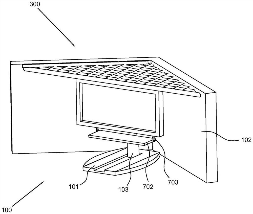
[0032] Such as Figure 1-7 , an adjustable bracket for alleviating long-term sitting postures for office work, including a support body 100, including a base plate 101, auxiliary plates 102 arranged on both sides of the base plate 101, and a telescopic member 103 connected to the display screen on the base plate 101; an angle adjustment assembly 200, including a connecting rod 201 arranged at the rear end of the display screen, a slider 202 arranged at the lower end of the connecting rod 201, and a chute 203 arranged at the upper end of the auxiliary board 102 to cooperate with the slider 202; and a storage assembly 300, the storage assembly 300 is set on the auxiliary board 102, the lower end of the display screen is provided with a retractable tray 602, the lower end of the display screen protrudes downwards from the first guide rail 603, and the retractable tray 602 is provided with a second guide rail matching the first guide rail 603.
[0033] Specifically, the main body ...
Embodiment 2
[0039] refer to Figure 1-6 , this embodiment is different from the first embodiment in that: the telescopic member 103 includes a first ring tube 103a arranged on the bottom plate 101, a second ring tube 103b slidably connected with the first ring tube 103a, and a second ring tube 103b connected with the second ring tube 103a. The third ring tube 103c connected to the tube 103b is slidably connected, the upper end of the third ring tube 103c is connected to the display screen in rotation, the rear end of the display screen is provided with a block 204, the block 204 is provided with a spherical groove 205, and the front end of the connecting rod 201 is provided with a The connecting ball 206 that cooperates with the spherical groove 205, the ball on the slider 202 is hinged with a piston 207, and the piston 207 is slidingly connected with the connecting rod 201, wherein a locking member 208 is provided between the piston 207 and the connecting rod 201, and the locking member ...
Embodiment 3
[0044] refer to Figure 1-6 This embodiment is different from the above embodiments in that: the storage assembly 300 includes a storage box 301 arranged on the auxiliary board 102, a storage cavity 302 opened in the storage box 301, and a storage opening opened on the storage box 301 303, the lower end of the storage box 301 protrudes downwards to have a number of storage clamping rods, and the clamping rings on the storage clamping rods, wherein, the upper end of the third ring tube 103c is provided with a rotating groove 305, and the lower end of the display screen is provided with a rotating groove that cooperates with the rotating groove 305. Block 306, a moving groove 400 is provided in the chute 203, the moving groove 400 communicates with the chute 203, and the sliding connection in the moving groove 400 is connected with a starting rod 401, and the starting rod 401 is provided with a first slope 402 near one end of the storage box, and the storage box A mating block i...
PUM
 Abstract
Description
Claims
Application Information
 - R&D
- Intellectual Property
- Life Sciences
- Materials
- Tech Scout
- Unparalleled Data Quality
- Higher Quality Content
- 60% Fewer Hallucinations
Browse by: Latest US Patents, China's latest patents, Technical Efficacy Thesaurus, Application Domain, Technology Topic, Popular Technical Reports.
© 2025 PatSnap. All rights reserved.Legal|Privacy policy|Modern Slavery Act Transparency Statement|Sitemap|About US| Contact US: help@patsnap.com


