
Ion source experiment platform

An experimental platform and ion source technology, applied in the performance research field of ion source performance research and ion source structure optimization, can solve the problems of difficult control of the positional relationship between the ion source and the magnetic pole surface, inaccurate research conclusions, and poor repeatability of experimental results. Achieve the effect of increasing the diversity of data collection, high experimental repeatability, and reducing the phenomenon of sparking

Pending Publication Date: 2021-09-17
四川玖谊源粒子科技有限公司
View PDF0 Cites 1 Cited by
  • Summary
  • Abstract
  • Description
  • Claims
  • Application Information

AI Technical Summary

Problems solved by technology

[0010] The purpose of the present invention is to provide a kind of ion source experimental platform, to solve the current traditional ion source platform proposed by the above-mentioned background technology, because the design of the magnetic pole surface is a pair of parallel surfaces up and down, the magnetic field lines produced are on the magnetic pole surface They are parallel to each other, which is not consistent with the distribution of magnetic field lines in a compact cyclotron. The research conclusions obtained by using the traditional ion source platform are not accurate. The magnet and the ion source vacuum chamber are separated, and there is movement in the experimental research. The relationship between the ion source assembly and the insertion of the vacuum chamber, the positional relationship between the ion source and the magnetic pole surface is difficult to control, so the repeatability of the experimental results is poor, etc.

Method used


Image

  • Ion source experiment platform
  • Ion source experiment platform
  • Ion source experiment platform

Examples


specific Embodiment

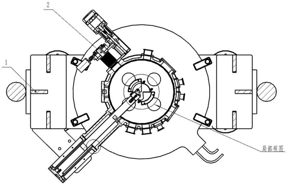
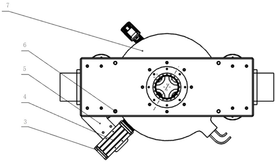
[0041] In this embodiment, when the hydraulic machine is turned on, the hydraulic cylinder will lift the upper magnetic pole 23, the upper cover plate, the upper magnetic yoke, the upper magnetic pole 23 and the coil 7, perform the uncapping process of the ion source platform, and then install the required External equipment for conducting ion source experiments and measuring experimental data, such as ion source 3, extraction electrodes, etc. When the experimental equipment is installed inside the vacuum box 20 and the equipment is positioned inside the vacuum chamber, the hydraulic cylinder is lowered, the contact between the bottom surface of the upper magnetic pole 23 and the vacuum box 20 is closed, the mechanical pump and the molecular pump are turned on, and the vacuum chamber is extracted. The internal air raises a high-vacuum vacuum condition for experiments to be carried out. When the vacuum reaches the experimental requirements, hydrogen gas is introduced into the a...


PUM


Abstract

The invention discloses an ion source experiment platform which comprises a coil module, a magnet structure module, an ion source module, a leading-out module, a vacuum module, a hydraulic module and an ion source platform supporting module. The coil module comprises a coil and a coil barrier strip, and the coil barrier strip is installed on the outer side of the coil; the magnet structure module comprises an upper cover plate, a lower cover plate, a first lower magnet yoke, a first upper magnet yoke, a second upper magnet yoke, a second lower magnet yoke, an upper magnetic pole, a boss and a lower magnetic pole, wherein the upper cover plate and the lower cover plate are located on the upper side and the lower side of the coil respectively. The ion source experiment platform ensures that the distribution of magnetic lines generated in the ion source experiment area is basically consistent with the distribution of magnetic lines in the central area of a compact cyclotron; the vacuum condition provided by the vacuum box can reach the magnitude of 10^-5Pa, the operation is easy, and the problem that the vacuum degree of a traditional ion source platform cannot be reached due to the structural design that the wall of a vacuum cavity is thin is solved.

Description

technical field [0001] The invention relates to the technical field of ion source performance research applied to compact cyclotrons, in particular to the technical field of performance research on ion source structure optimization, specifically an ion source experimental platform. Background technique [0002] The ion source is used to generate the beam in the cyclotron, which is called the heart of the cyclotron. The performance indicators of the ion source include parameters such as beam intensity, beam stability, and optimal working airflow. Among them, the most important performance index of the ion source is the beam intensity. In order to study the performance of the ion source, it is essential to consider the intensity of the beam that the ion source can produce, and a platform is needed that is specially used to study the yield of the beam intensity that the ion source can produce. [0003] Since the ion source used in the compact cyclotron belongs to the type of ...

Claims


Application Information

Patent Timeline
Patent Type & Authority Applications(China)
IPC IPC(8): H05H1/00
CPCH05H1/0087Y02E30/10
Inventor 石金水陈宇航张聪王丹邓建军马瑞利
Owner 四川玖谊源粒子科技有限公司
Learn More