
Intelligent building capable of automatically controlling lighting quantity

A technology of intelligent buildings and mobile panels, which is applied in the direction of construction, building structure, general water supply conservation, etc. It can solve the problems of no snow removal function, poor lighting ability, and poor snow resistance of square high sheds.

Inactive Publication Date: 2021-09-17
CHANGSHA UNIVERSITY OF SCIENCE AND TECHNOLOGY
View PDF10 Cites 0 Cited by
  • Summary
  • Abstract
  • Description
  • Claims
  • Application Information

AI Technical Summary

Problems solved by technology

[0002] Due to the unique geographical location and environment in the north, the cultivation of vegetables needs to rely on agricultural greenhouses to increase production. The agricultural greenhouses have developed from the original low and small sheds to square high sheds, but square high sheds often collapse due to poor snow resistance. After many times of reconstruction and trials, it developed into the existing arched greenhouse. However, the snow resistance ability of the arched greenhouse is still challenged, and it does not have the function of snow removal. Therefore, in the snowy northern region, its lighting ability Poor, thus inconvenient to use

Method used


Image

  • Intelligent building capable of automatically controlling lighting quantity
  • Intelligent building capable of automatically controlling lighting quantity
  • Intelligent building capable of automatically controlling lighting quantity

Examples


Embodiment Construction

[0012] In order to make the purpose, technical solutions and advantages of the embodiments of the present invention clearer, the technical solutions in the embodiments of the present invention will be clearly and completely described below in conjunction with the drawings in the embodiments of the present invention. Obviously, the described embodiments It is a part of embodiments of the present invention, but not all embodiments. Based on the embodiments of the present invention, all other embodiments obtained by persons of ordinary skill in the art without creative efforts fall within the protection scope of the present invention.

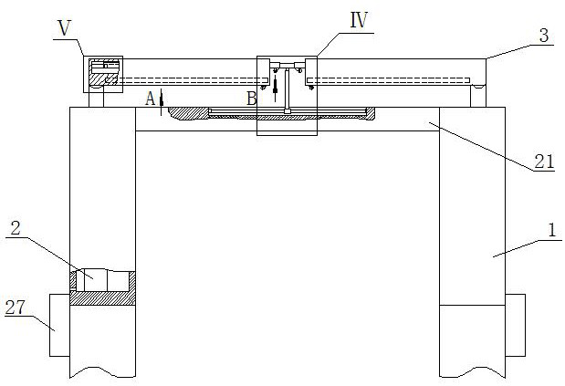
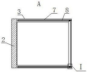
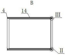
[0013]An intelligent building that automatically controls the amount of daylight, as shown in the figure, includes two long strips 1, each strip 1 is installed on the top of the vertical wall of the greenhouse, and the top of the strip 1 is provided with a groove. A plurality of waterproof telescopic rods 2 are arranged in the groove, and the mova...


PUM


Abstract

The invention relates to an intelligent building capable of automatically controlling the lighting quantity. The intelligent building comprises two long-strip-shaped plates, grooves are formed in the top ends of the long-strip-shaped plates, a plurality of waterproof telescopic rods are arranged in the grooves in a matched mode, the top ends of movable rods of the plurality of waterproof telescopic rods located in the same groove are connected in a hinged mode through a first movable plate, and a first through groove is formed in the top end of the first movable plate; glass is fixedly mounted at the upper and lower ends of the first through groove; and placing grooves are formed in the inner walls of the front and rear ends of the middle of the first through groove. According to the intelligent building, the angles of the first movable plate and the second movable plates can be adjusted according to different illumination in the greenhouse, the direction of sunlight entering the greenhouse is selected, meanwhile, the lighting quantity can be controlled according to the requirements of plants, a greenhouse film on the lower portion can be protected through the first movable plate and the second movable plates, and the greenhouse film is prevented from being damaged. In addition, in snowy weather, the smaller the angle between the two second movable plates is, the faster the snow slides off from the first movable plate and the second movable plates, and the influence of snow disasters is avoided.

Description

technical field [0001] The invention belongs to the technical field of agricultural buildings, in particular to an intelligent building that automatically controls the amount of daylighting. Background technique [0002] Due to the unique geographical location and environment in the north, the cultivation of vegetables needs to rely on agricultural greenhouses to increase production. The agricultural greenhouses have developed from the original low and small sheds to square high sheds, but square high sheds often collapse due to poor snow resistance. After many times of reconstruction and trials, it developed into the existing arched greenhouse. However, the snow resistance ability of the arched greenhouse is still challenged, and it does not have the function of snow removal. Therefore, in the snowy northern region, its lighting ability Poor and thus inconvenient to use. Contents of the invention [0003] The invention provides an intelligent building that automatically ...

Claims


Application Information

Patent Timeline
Patent Type & Authority Applications(China)
IPC IPC(8): A01G9/14A01G9/22A01G9/24E03B3/02E04D13/10
CPCA01G9/14A01G9/227A01G9/22A01G9/247A01G9/24E03B3/02E04D13/106A01G2009/1492Y02A20/108Y02A40/25
Inventor 何川熊颖林业达禹丽娥
Owner CHANGSHA UNIVERSITY OF SCIENCE AND TECHNOLOGY
Learn More