Soil taking and hole forming device and hole forming method based on reverse rotation

A technology for forming holes and installing plates, which is applied in planting methods, excavation/covering trenches, agriculture, etc., and can solve the problems of large changes in the size of formed holes, decreased air permeability between soil particles around the holes, and transplanting of seedlings in pots. The depth is difficult to meet the agronomic requirements and other issues

Active Publication Date: 2022-03-08
HUNAN AGRICULTURAL UNIV
View PDF8 Cites 0 Cited by
  • Summary
  • Abstract
  • Description
  • Claims
  • Application Information

AI Technical Summary

Problems solved by technology

[0003] At present, most of the cavitation devices have the influence of the forward speed of the machine tool and the influence of the cavitation operation mode
Poor advance speed of the machine will cause large disturbance to the soil during the hole forming process and a large change in the size of the formed hole; the existing poor hole forming operation method will cause problems such as more soil returning in the hole and a decrease in the porosity of the hole wall soil. The above problems will lead to The uprightness and planting depth of transplanting pot seedlings are difficult to meet the agronomic requirements, and the air permeability between soil particles around the holes decreases, which affects the growth quality of rapeseed pot seedlings in the holes, and affects the effect of hole forming operation of the hole-making transplanter and the effect of potting. Seedling transplanting quality had adverse effects

Method used


Image

  • Soil taking and hole forming device and hole forming method based on reverse rotation
  • Soil taking and hole forming device and hole forming method based on reverse rotation
  • Soil taking and hole forming device and hole forming method based on reverse rotation

Examples


Embodiment 1

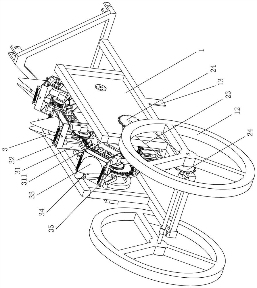
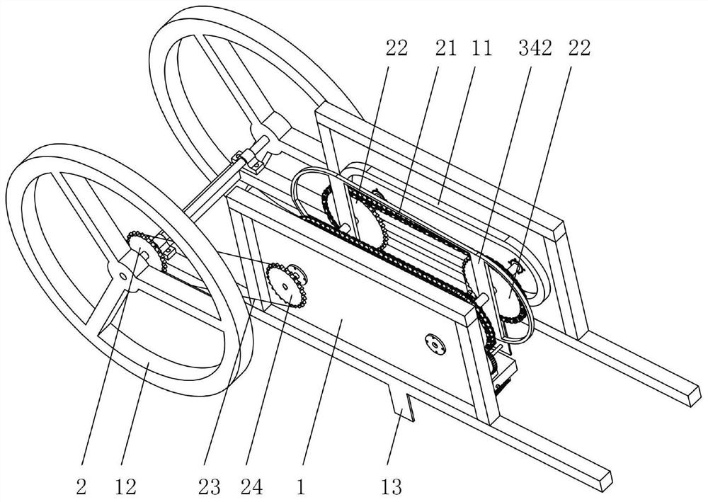
[0036] Such as figure 1 with figure 2 As shown, the soil-taking and caving-forming device based on reverse rotation in this embodiment includes a frame 1, a transmission mechanism 2, and a soil-taking and caving-forming mechanism 3. The mechanism 3 travels; the vertical plane parallel to the walking direction in the frame 1 is provided with a rotary closed track 11, the soil-taking and caving mechanism 3 is slid on the track 11, and the transmission mechanism 2 is driven by the walking motion of the frame 1. The soil-taking and caving mechanism 3 slides around the track 11; the rail 11 is provided with a first rail section parallel to the ground, and the sliding direction of the soil-taking and caving mechanism 3 on the first rail section is opposite to the walking direction of the frame 1 and Make holes in the ground.

[0037]In the hole making process, the running direction of the soil-taking and forming-caving mechanism 3 on the track 11 is opposite to the walking direct...

Embodiment 2

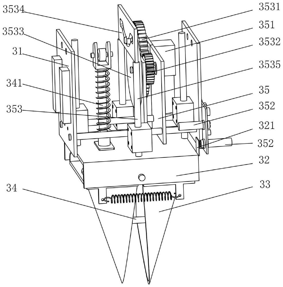
[0064] The present embodiment provides the operating cycle of the soil-taking and caving-forming mechanism 3:

[0065] When the soil-taking and caving-forming mechanism 3 performs rotary motion along the track 11 and has not yet entered the caving stage, the photoelectric switch 352 is not triggered, the motor 351 is in a non-working state, and the rotating disk 3533, chute plate 3534, push rod 341, cam 342 and Parts such as the soil-borrowing sheet are in a relatively static state. At this time, the roller shaft of the rotating disk 3533 is in the symmetrical center position of the chute plate 3534, and the soil-taking piece 33 and the push rod 341 are all at the beginning position of the soil-entry stage of the cam 342. Contact with the outer contour of the cam 342 all the time, and the soil-taking piece 33 is in an open posture.

[0066] When the motor 351 rotates, it drives the first gear 3531 and the second gear 3532 meshed with it to rotate, and the second gear 3532 dri...


PUM


Abstract

The invention discloses a device for taking soil and forming a hole based on reverse rotation and a method for forming a hole. The device for forming a hole includes a frame, a transmission mechanism and a mechanism for taking soil and forming a hole. The soil-taking and caving mechanism walks; the frame is provided with a rotary closed track on a vertical plane parallel to the walking direction, and the soil-taking and caving mechanism is slid on the rail, and the transmission mechanism drives the feeding mechanism through the walking motion of the frame. The soil caving mechanism slides around the track; the rail is provided with a first rail segment parallel to the ground, and the sliding direction of the soil caving mechanism on the first rail segment is opposite to the running direction of the frame and facing the ground Punch. The soil-taking cavitation device based on reverse rotation of the present invention has the advantages of simple structure, convenient use, reasonable mechanical operation, and high caving quality. The cavitation method using the cavitation device has the advantages of high operating efficiency and reasonable stroke configuration.

Description

technical field [0001] The invention relates to the technical field of agricultural machinery and equipment, in particular to a device for taking soil and forming a hole based on reverse rotation and a method for forming a hole. Background technique [0002] Rapeseed is an important oil crop, and the rapeseed oil it produces accounts for about 40% of the vegetable oil consumed by Chinese residents. my country's rapeseed planting area reaches 7 million hectares, with a total output of 12 million tons, ranking first in the world. At present, there are two main modes of rapeseed planting: planting and transplanting. The planting of rapeseed in the Yangtze River Basin still follows the mode of transplanting rapeseed; most of the existing rapeseed transplanting is done manually by pure labor, and the overall economic benefits are low. Mechanized pot seedling transplanting of rapeseed can not only alleviate the crop stubble conflict, but also have the advantages of mechanized ope...

Claims


Application Information

Patent Timeline
Patent Type & Authority Patents(China)
IPC IPC(8): A01C5/04
CPCA01C5/04
Inventor 吴明亮全伟蒋啸虎杨安明代振维
Owner HUNAN AGRICULTURAL UNIV
Why Eureka
Try Eureka