Cleaning device and cleaning method of garbage in valve

A garbage cleaning and valve technology, applied in valve device, valve operation/release device, separation method, etc., can solve problems such as inability to clean up in time, single valve function, and increased labor intensity.

Inactive Publication Date: 2021-09-14
山东口天环保设备科技有限责任公司
View PDF0 Cites 0 Cited by
  • Summary
  • Abstract
  • Description
  • Claims
  • Application Information

AI Technical Summary

Problems solved by technology

[0002] Sewage treatment and water recycling are important components of the field of environmental protection. With the rapid development of the domestic economy, sewage treatment and water recycling are important components of the field of environmental protection. With the rapid development of the domestic economy and the improvement of residents' living standards, the annual industrial The discharge of sewage and domestic sewage is also increasing. Sewage treatment needs to be controlled by drainage valves. However, after a period of use, the existing drainage valves will be blocked due to dirt entangled on the surface of the valve core.
[0003] However, the functions of the existing valves are relatively single, and it is impossible to clean them in time, and it is necessary to stop the water to clean the valves, which not only increases the labor intensity, but also causes a sharp drop in work efficiency due to the water stop, which affects the valve The normal flow of water has brought a lot of inconvenience

Method used


Image

  • Cleaning device and cleaning method of garbage in valve
  • Cleaning device and cleaning method of garbage in valve
  • Cleaning device and cleaning method of garbage in valve

Examples


Embodiment Construction

[0032] Embodiments of the present invention are described in detail below, examples of which are shown in the drawings, wherein the same or similar reference numerals designate the same or similar elements or elements having the same or similar functions throughout. The embodiments described below by referring to the figures are exemplary only for explaining the present invention and should not be construed as limiting the present invention.

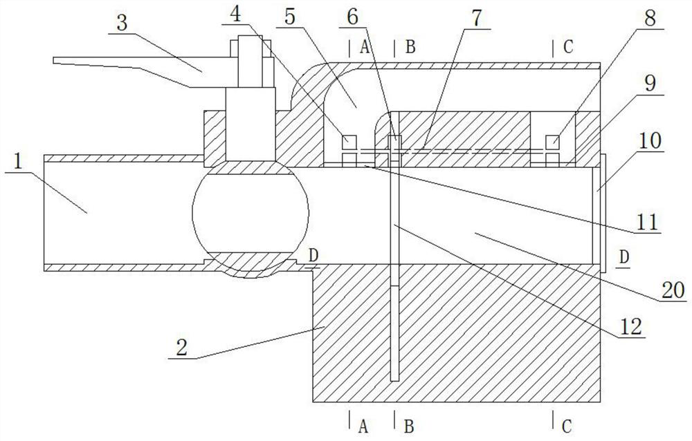
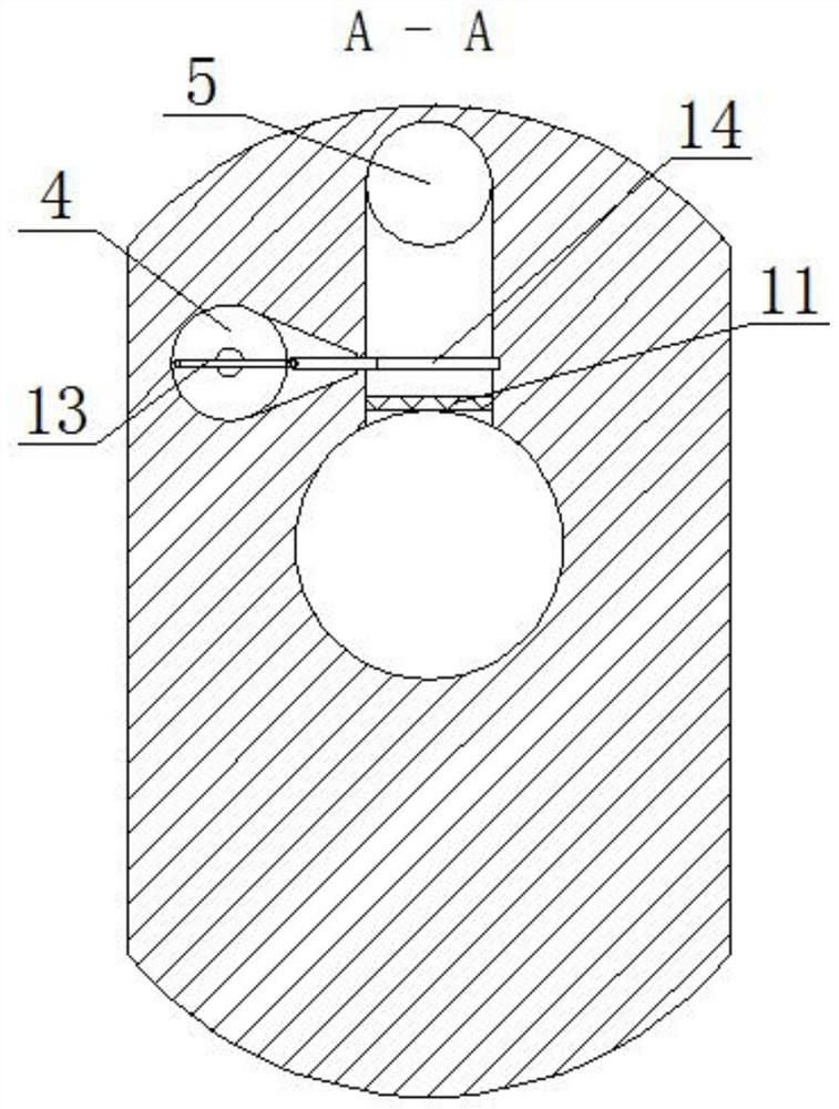
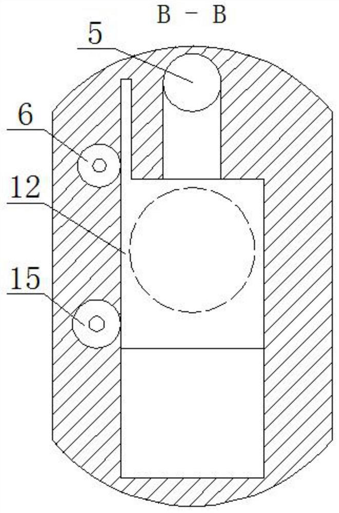
[0033] Such as Figure 1-6 As shown, this embodiment proposes a garbage cleaning device in the valve, including a ball valve 2, a large baffle 12 is slidably connected inside the ball valve 2, and the large baffle 12 divides the internal space of the ball valve 2 into the water inlet space 1 and the left side. Clearance space 20 on the right. The ball valve 2 is also rotatably connected with a wrench 3, and the wrench 3 is used to open or close the water inlet space 1. The wrench 3 is an inherent mechanism of the ball valve 2 to realiz...


PUM


Abstract

The invention discloses a cleaning device and cleaning method of garbage in a valve. The device comprises a ball valve, a large baffle is connected into the ball valve in a sliding mode, and the large baffle divides an inner space of the ball valve into a water inlet space on the left side and a cleaning space on the right side; a water outlet space is further formed above the ball valve, the cleaning space communicates with the water outlet space through a second filter screen, a second baffle connected with the ball valve in a sliding mode is arranged above the second filter screen, and the water outlet space is arranged above the second baffle; a second main shaft is rotationally connected in the ball valve, a second rotating wheel is fixedly connected to the right end of the second main shaft in a sleeving mode, a second connecting rod is eccentrically hinged to the second rotating wheel, and the other end of the second connecting rod is hinged to the second baffle; and the second main shaft is connected with a first driving mechanism, the large baffle is connected with a second driving mechanism, and a slag removing opening is formed in the right side of the cleaning space. While cleaning work is carried out, normal passing of water flow is not affected, the service life of the valve is prolonged, the cleaning difficulty is lowered, the probability that waste blocks a pipeline is lowered, and the working efficiency is improved.

Description

technical field [0001] The invention relates to the technical field of valves, in particular to a garbage cleaning device and a cleaning method in a valve. Background technique [0002] Sewage treatment and water recycling are important components of the field of environmental protection. With the rapid development of the domestic economy, sewage treatment and water recycling are important components of the field of environmental protection. With the rapid development of the domestic economy and the improvement of residents' living standards, the annual industrial The discharge of sewage and domestic sewage is also increasing, and sewage treatment needs to be controlled by drainage valves. However, after a period of use, the existing drainage valves will be blocked due to dirt entangled on the surface of the valve core. [0003] However, the functions of the existing valves are relatively single, and it is impossible to clean them in time, and it is necessary to stop the wat...

Claims


Application Information

Patent Timeline
IPC IPC(8): F16K3/02F16K3/30F16K5/06F16K27/00F16K31/60F16K43/00B01D35/04
CPCF16K3/02F16K3/30F16K5/06F16K27/00F16K31/60F16K43/00B01D35/04
Inventor 刘淑英
Owner 山东口天环保设备科技有限责任公司
Why Eureka
Try Eureka