Buoyancy generator

A generator and buoyancy technology, applied in the direction of engine components, machines/engines, mechanical equipment, etc., can solve the problems of unenvironmental protection, high energy consumption of generators, and large pollution.

Inactive Publication Date: 2021-09-14
陆善珍
View PDF0 Cites 0 Cited by
  • Summary
  • Abstract
  • Description
  • Claims
  • Application Information

AI Technical Summary

Problems solved by technology

[0004] In view of this, in order to solve the technical problems of high energy consumption, heavy pollution, and non-environmental protection of generators in the prior art, the present invention provides a buoyancy generator with simple structure, reasonable design, convenient operation, self-produced electric energy, environmental protection and no pollution

Method used


Image

  • Buoyancy generator
  • Buoyancy generator
  • Buoyancy generator

Examples


Embodiment Construction

[0033] Embodiments of the present invention are described in detail below, examples of which are shown in the drawings, wherein the same or similar reference numerals designate the same or similar elements or elements having the same or similar functions throughout. The embodiments described below by referring to the figures are exemplary and are intended to explain the present invention and should not be construed as limiting the present invention.

[0034] In describing the present invention, it is to be understood that the terms "upper", "lower", "front", "rear", "left", "right", "vertical", "horizontal", "top", The orientation or positional relationship indicated by "bottom", "inner", "outer", etc. is based on the orientation or positional relationship shown in the drawings, and is only for the convenience of describing the present invention and simplifying the description, rather than indicating or implying the referred device or positional relationship. Elements must hav...


PUM


Abstract

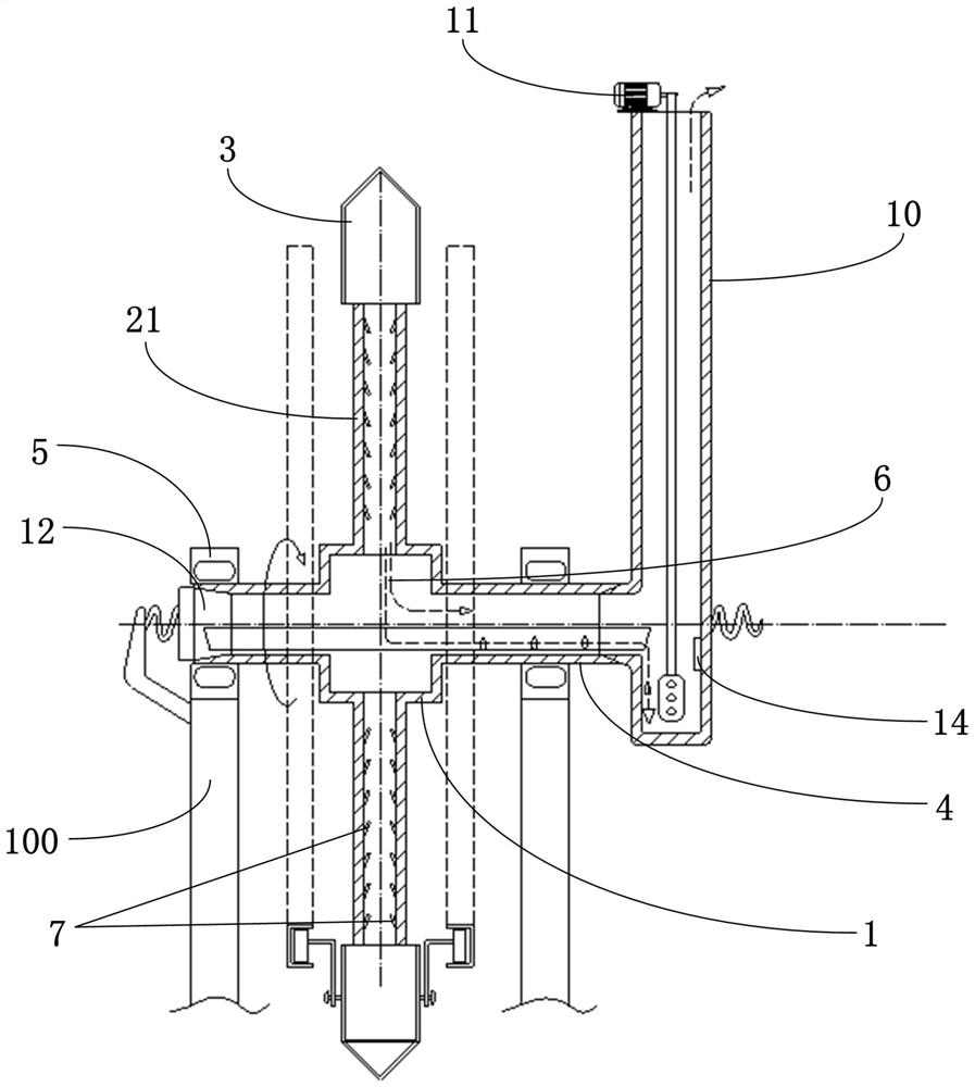
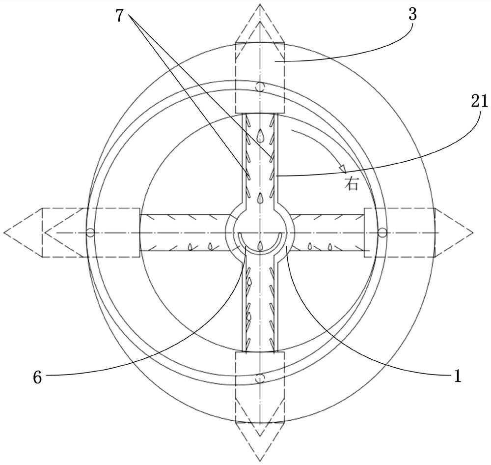
The invention discloses a buoyancy generator. The buoyancy generator is arranged on a supporting frame and comprises a rotating wheel, rotating rods and floating barrels, wherein the rotating wheel is rotationally connected to the supporting frame through a connecting pipe and a rotating bearing, and a water receiving groove is formed inside the rotating wheel; the plurality of rotating rods are evenly arranged on the same circumferential face, one ends of the rotating rods are connected to the circumferential side wall of the rotating wheel, a hollow flow channel is formed inside each rotating rod, the hollow flow channels communicate with the interior of the rotating wheel, and flow guide plates which are obliquely arranged are arranged on the side walls of the hollow flow channels; and the plurality of floating barrels are arranged, the plurality of floating barrels and the plurality of rotating rods are arranged in a one to one correspondence mode correspondingly, one end of each floating barrel is arranged on the side wall of the other end of the corresponding rotating rod in an attached mode and connected with the corresponding rotating rod in a sliding mode, and the other end of each floating barrel forms a closed tip cylindrical structure. The buoyancy generator is simple in structure, reasonable in design, convenient to operate, free of additional combustion of other fuels, free of pollution, free of waste residues, free of noise and free of energy supply in the power generation process, and environment-protecting.

Description

technical field [0001] The invention relates to the technical field of power generation equipment, and more specifically relates to a buoyancy generator which converts buoyancy of water into power. Background technique [0002] With the advancement of science and technology, people continue to develop various types and uses of engines, but no matter what kind of engine, its basic premise is to use some kind of fuel to generate power. Large environmental pollution and poor environmental protection are not conducive to long-term development. [0003] Therefore, it is an urgent problem for those skilled in the art to provide a buoyancy generator with simple structure, reasonable design, no pollution, environmental protection, buoyancy of water used for power generation, and effectively solving the problem of resource scarcity. Contents of the invention [0004] In view of this, in order to solve the technical problems of high energy consumption, heavy pollution, and non-envi...

Claims


Application Information

Patent Timeline
Patent Type & Authority Applications(China)
IPC IPC(8): F03B17/04
CPCF03B17/04
Inventor 赵敏杰
Owner 陆善珍
Why Eureka
Try Eureka