High and steep soil slope underneath pass parallel tunnel bias pressure treatment method and rapid measurement device

A technology for soil slopes and measuring devices, which can be used in tunnels, earthwork drilling, mining devices, etc., and can solve problems such as shaking, measurement errors, and confusion at the construction site

Active Publication Date: 2021-09-14
WUHAN UNIV OF TECH
View PDF4 Cites 0 Cited by
  • Summary
  • Abstract
  • Description
  • Claims
  • Application Information

AI Technical Summary

Problems solved by technology

In application and actual engineering, for steep soil slopes with steep slopes, the above support methods still cannot effectively solve the problem of tunnel bias, and due to the chaos of the construction site, displacement observation piles are often damaged or shaken. large error in measurement

Method used


Image

  • High and steep soil slope underneath pass parallel tunnel bias pressure treatment method and rapid measurement device
  • High and steep soil slope underneath pass parallel tunnel bias pressure treatment method and rapid measurement device
  • High and steep soil slope underneath pass parallel tunnel bias pressure treatment method and rapid measurement device

Examples


Embodiment 1

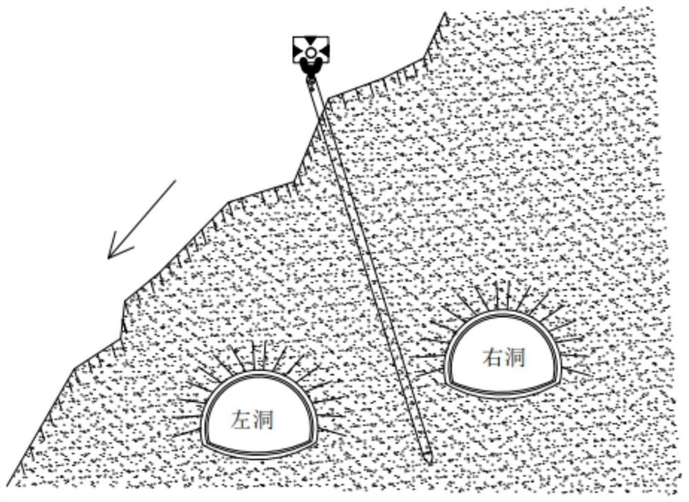
[0041] A certain tunnel project is a separated short tunnel crossing the mountain formed after the excavation of the mountain. The overall direction of the tunnel is about 310 meters. The hole is shallow buried side. The ridge crossed by the tunnel is high in the south and low in the north (such as figure 1 As shown), according to the analysis of bias conditions based on the lateral slope of the topography of the cave and the buried depth of the tunnel, there is a phenomenon of bias pressure in the tunnel; the excavation of the right hole has a footage of 8 meters and the left hole collapses when the left hole is excavated. After the excavation, the monitoring data in the cave changed greatly, and the side slope bias effect of the cave entrance was more obvious. Therefore, according to the tunnel design drawings, the steel pipe piles are obliquely pressed into the slope (such as figure 1 As shown), the expected route of the steel pipe pile 9 is pre-designed, the starting poi...

Embodiment 2

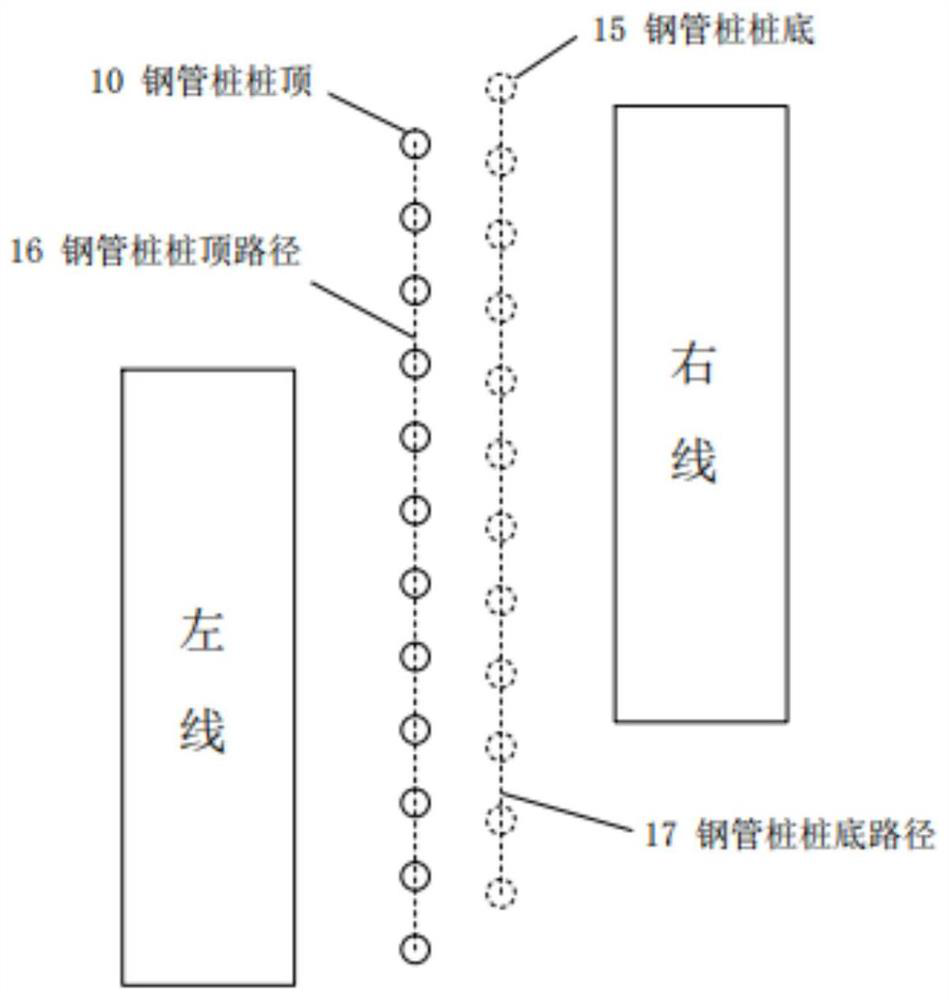
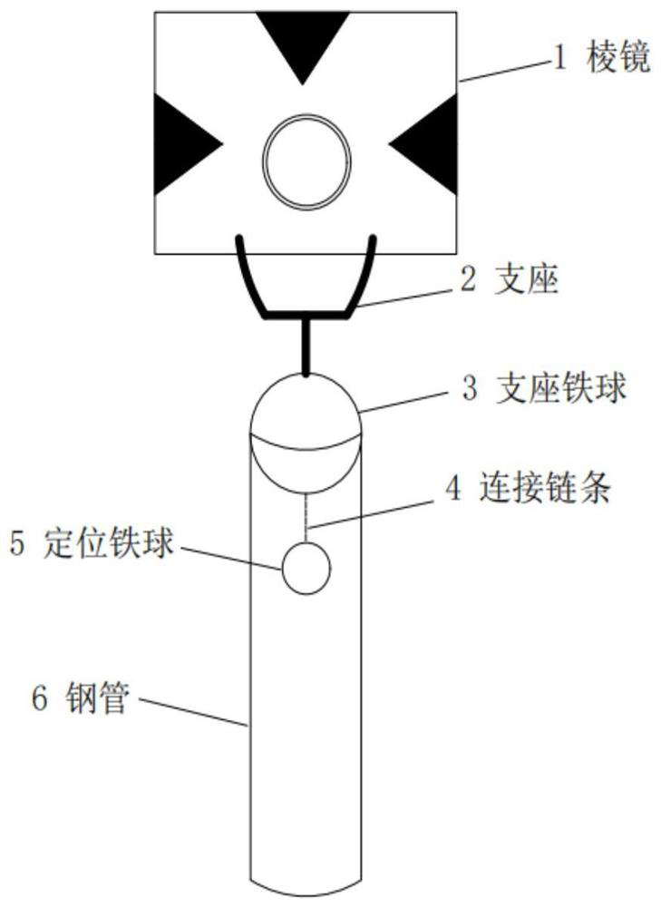
[0045] A bias pressure phenomenon occurs during the construction of a steeply inclined slope passing through a parallel tunnel with a small clear distance. Now, a fourth-order counter-pressure retaining slope is piled up at the entrance of the bias-pressure side as a support, and the second and fourth steps of the slope are set. Rapid measuring devices such as Figure 4 As shown, as the displacement observation measuring point. When the soil in the upper part of the right hole slides to the left side, the back pressure retaining slope is subjected to a downward force along the slope surface, and the steel pipe 6 on the slope shifts with the soil, causing the iron ball 3 of the upper support to follow the steel pipe 6 The position of the lower positioning iron ball 5 is driven by gravity to keep the upper support iron ball always in a vertical state, so that the coordinates of the center point of the upper prism are only caused by the sliding of the slope surface, which avoids ...


PUM


Abstract

The invention discloses a high and steep soil slope underneath pass parallel tunnel bias pressure treatment method and a rapid measurement device. The method comprises the steps that 1) bias pressure condition analysis is carried out, and specifically, a back pressure soil retaining slope is accumulated at a sliding side tunnel portal of a bias pressure soil body; 2) the rapid measurement device for measuring deformation data of the back pressure soil retaining slope is embedded; 3) an expected steel pipe pile supporting and retaining line is designed; 4) displacement observation is conducted on the back pressure soil retaining slope and a steel pipe pile; and 5) the consolidation degree of the soil under the slope is calculated according to the observation result, the pre-pressing time is determined, and a stable support is formed. According to the treatment method, the problem of tunnel bias pressure on a steeply inclined soil slope is solved, the reverse pressure slope arranged on the shallow buried side has a dispersion effect on the tunnel bias pressure effect and has a reverse pressure effect on the soil body on the shallow buried side, operation is easy, later maintenance is convenient, and the supporting effect is remarkable.

Description

technical field [0001] The invention relates to the technical field of deformation monitoring of high and steep slopes, in particular to a method for controlling the bias pressure of parallel tunnels passing down high and steep soil slopes and a rapid measuring device. [0002] technical background [0003] Due to objective reasons such as topography, geomorphology, and geological relations, the surrounding rock pressure will appear significantly inhomogeneous during tunnel excavation, which will have adverse effects on tunnel support and construction under the action of eccentric loads. When there is a discrepancy between the tunnel slope design and the actual construction situation, reasonable adjustments should be made in accordance with the principle of "dynamic design and dynamic construction". In order to solve this kind of problem, the support methods commonly used at present include surface grouting method, slope cutting and drainage method, decompression or counter p...

Claims


Application Information

Patent Timeline
Patent Type & Authority Applications(China)
IPC IPC(8): E21F17/18E21F17/00E21D11/10E21D9/14
CPCE21F17/18E21F17/00E21D11/10E21D9/14
Inventor 李新平王婧甘鑫郭运华龚航里裴晨浩黄文旭沙剑鸣
Owner WUHAN UNIV OF TECH
Why Eureka
Try Eureka