CO2 injection and production method, electronic equipment and medium

An electronic device and technology for injecting wells, which can be used in the fields of fluid extraction, earthwork drilling, wellbore/well components, etc., and can solve problems such as limited water injection capacity, ineffective effects, and decreased gas absorption capacity of formations.

Pending Publication Date: 2021-09-14
CHINA PETROLEUM & CHEM CORP +1
View PDF8 Cites 0 Cited by
  • Summary
  • Abstract
  • Description
  • Claims
  • Application Information

AI Technical Summary

Problems solved by technology

Although these methods can achieve certain effects, many problems have been exposed in the field implementation process, such as water-air alternation, and the injected water will occupy a part of the reservoir pore volume, reducing the gas storage space and CO 2 At the same time, due to the poor physical properties of low-permeability reservoirs, the water injection capacity is limited, and the water injection also reduces the phase permeability of the gas phase, weakening the gas injection capacity
Gel and other types of plugging agents have limited ability to adjust the suction profile, and sometimes it is easy to block the formation, resulting in a sharp drop in the gas absorption capacity of the formation, and most of the plugging agents have a short validity period
Current CO 2 It is difficult to fundamentally solve the problem with flooding, injection and production control methods, and often the effect of treatment is not obvious

Method used


Image

  • CO2 injection and production method, electronic equipment and medium
  • CO2 injection and production method, electronic equipment and medium
  • CO2 injection and production method, electronic equipment and medium

Examples


Embodiment Construction

[0026] The present invention will be described in more detail below with reference to the accompanying drawings. Although preferred embodiments of the invention are shown in the drawings, it should be understood that the invention may be embodied in various forms and should not be limited to the embodiments set forth herein. Rather, these embodiments are provided so that this disclosure will be thorough and complete, and will fully convey the scope of the invention to those skilled in the art.

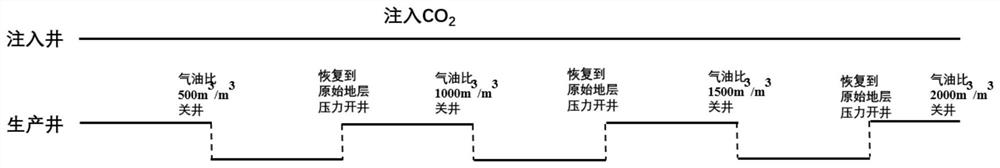
[0027] figure 1 shows the CO according to the present invention 2 A flowchart of the steps of the injection-production method.

[0028] In this example, CO according to the present invention 2 The injection-production method may include: step 101, setting the pressure threshold, gas-oil ratio threshold, and production shutdown threshold; step 102, continuously injecting CO into the injection well 2 , the production well is producing; step 103, the gas-oil ratio reaches the gas-oil ...


PUM


Abstract

The invention discloses a CO2 injection and production method, electronic equipment and a medium. The method can comprise the steps that the original formation pressure is determined, and a gas-oil ratio threshold value and a production halt threshold value are set; CO2 is continuously injected into an injection well, and a production well conducts production; the formation pressure and the gas-oil ratio of a wellhead of the production well are monitored in real time; when the gas-oil ratio reaches the gas-oil ratio threshold value, the production well stops production; and when the formation pressure is restored to the original formation pressure, the production well restores production till the gas-oil ratio reaches the production halt threshold value, and the production well and the injection well both stop working. According to the CO2 injection and production method, the electronic equipment and the medium, through the control mode of continuous CO2 injection of the injection well and intermittent production of the production well, the CO2 swept volume is increased, gas channeling is prevented, formation pressure decreasing is relieved, the oil well productivity is improved, accordingly, the CO2 flooding production effect is improved, CO2 flooding benefit development is achieved, and good application prospects are achieved.

Description

technical field [0001] The present invention relates to the field of oil recovery, more specifically, relates to a CO 2 Injection and production methods, electronic equipment and media. Background technique [0002] Carbon dioxide flooding is a mature oil recovery technology, which can realize carbon sequestration while oil displacement is used, and has both economic and environmental benefits. CO 2 Oil flooding technology has a development history of more than 60 years. According to incomplete statistics, there are nearly 80 carbon dioxide flooding projects being implemented around the world. CO 2 The application of drive is also accompanied by many problems. Among them, CO has a greater impact on recovery 2 Drive away the gas. Whether gas channeling can be suppressed and blocked is the key factor for the success of gas injection development, because once gas channeling occurs, it will not only waste manpower, material and financial resources, but also cause indelible...

Claims


Application Information

Patent Timeline
Patent Type & Authority Applications(China)
IPC IPC(8): E21B43/16E21B43/18
CPCE21B43/164E21B43/18Y02P90/70
Inventor 周元龙赵淑霞何应付王锐马涛
Owner CHINA PETROLEUM & CHEM CORP
Why Eureka
Try Eureka