An embroidery machine presser foot control system

A technology of control system and motor control, which is applied in the field of embroidery machines, can solve the problems of unified spindle, difficulty of presser foot, and deviation of presser foot lift, so as to ensure the safety of equipment

Active Publication Date: 2022-05-06
浙江玛雅机电科技有限公司
View PDF0 Cites 0 Cited by
  • Summary
  • Abstract
  • Description
  • Claims
  • Application Information

AI Technical Summary

Problems solved by technology

[0004] At present, the presser foot is independently driven by a separate motor to directly control the presser foot. The presser foot moves up and down between the preset highest position and the cloth press position. Because the spindle speed that drives the needle bar moves constantly changes, it is difficult for the presser foot to keep pace with the spindle. Completely unified, the presser foot will deviate when it is raised and lowered, resulting in lower precision of the presser foot. Therefore, it is necessary to provide a presser foot control system for embroidery machines to ensure that the presser foot and the needle bar move synchronously.

Method used


Image

  • An embroidery machine presser foot control system

Examples


Embodiment Construction

[0015] The present invention will be further described below in conjunction with specific embodiments, wherein, the accompanying drawings are only for exemplary illustration, and what represent is only a schematic diagram, rather than a physical map, and cannot be understood as a limitation to this patent; in order to better illustrate the present invention In the embodiments, certain components in the drawings may be omitted, enlarged or reduced, and do not represent the size of the actual product; it is understandable to those skilled in the art that some known structures and their descriptions in the drawings may be omitted.

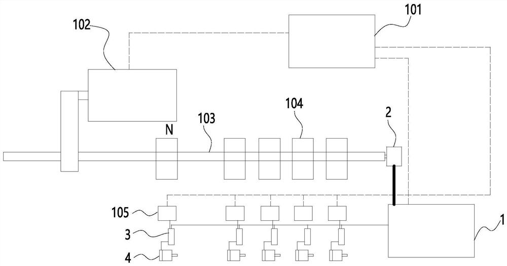
[0016] refer to figure 1 As shown, an embroidery machine generally includes a main control system 101 , a main motor 102 , a main shaft 103 , a machine head 104 and a machine head control board 105 . The main control system 101 mainly completes data input and output, processing, analysis, and coordinated control, and directly controls the main motor 1...


PUM


Abstract

The present invention relates to the technical field of embroidery machines, and discloses an embroidery machine presser foot control system, which includes a controller, a spindle encoder, a presser foot motor control board and a presser foot motor. The control board is connected with the main control system, and the presser motor control board is connected with the presser motor and the machine head control board. The spindle encoder is used to detect the working state and position of the spindle, and send the signal to the controller; the controller is used to send the signal of the spindle encoder to the main control system and the presser motor control board, and disconnect the main control The spindle encoder signal obtained by the system stops the embroidery machine from working. The embroidery machine presser foot control system and the main control system of the present invention are independent of each other, and the working state of the embroidery machine can be automatically judged by obtaining the signal of the main shaft encoder, the lock signal and the mending embroidery signal, and the above signals and the working state of the embroidery machine can be Accurately control the synchronous movement of the presser foot and the needle bar, and can also actively disconnect the signal of the main shaft encoder to stop the embroidery machine, ensuring the safety of the equipment of the embroidery machine.

Description

technical field [0001] The invention relates to the technical field of embroidery machines, and in particular discloses an embroidery machine presser foot control system. Background technique [0002] Embroidery machine, also known as embroidery machine, is an advanced embroidery machine in modern times. It can achieve high-speed and high-efficiency traditional manual embroidery, and can also achieve "multi-level, multi-functional, uniform and harmonious" that cannot be achieved by manual embroidery. perfection" requirement. It is an electromechanical product that embodies a variety of high-tech. As computer embroidery replaces manual embroidery, embroidery machines will also become the main models in the embroidery industry. [0003] During the working process of the embroidery machine, the power device drives the needle bar to move up and down through the transmission mechanism to realize embroidery. In order to compress the fabric, the needle bar frame is also provided...

Claims


Application Information

Patent Timeline
Patent Type & Authority Patents(China)
IPC IPC(8): D05C9/20
CPCD05C9/20
Inventor 王亮俞永刚徐伟成宣东良王立庆
Owner 浙江玛雅机电科技有限公司
Why Eureka
Try Eureka