
Jig rotating device and circulating method for permanent magnet direct-current motor and motor assembling equipment

A technology of rotating device and permanent magnet DC, which is applied in the direction of electromechanical devices, electric components, assembly machines, etc., and can solve the problem of inaccurate loading of the mandrel into the casing.

Inactive Publication Date: 2021-09-14
陈荣乾
View PDF1 Cites 2 Cited by
  • Summary
  • Abstract
  • Description
  • Claims
  • Application Information

AI Technical Summary

Problems solved by technology

[0005] The purpose of the present invention is to solve the problems in the prior art that the mandrel is not accurately loaded into the casing, and the direction of the motor assembly needs to be changed, and proposes a permanent magnet that uses two jigs, is suitable for the mandrel to be loaded, and is loaded with high precision. DC motor fixture rotating device

Method used


Image

  • Jig rotating device and circulating method for permanent magnet direct-current motor and motor assembling equipment
  • Jig rotating device and circulating method for permanent magnet direct-current motor and motor assembling equipment
  • Jig rotating device and circulating method for permanent magnet direct-current motor and motor assembling equipment

Examples


Embodiment Construction

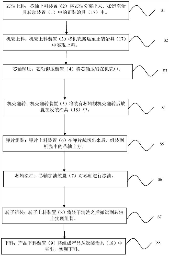
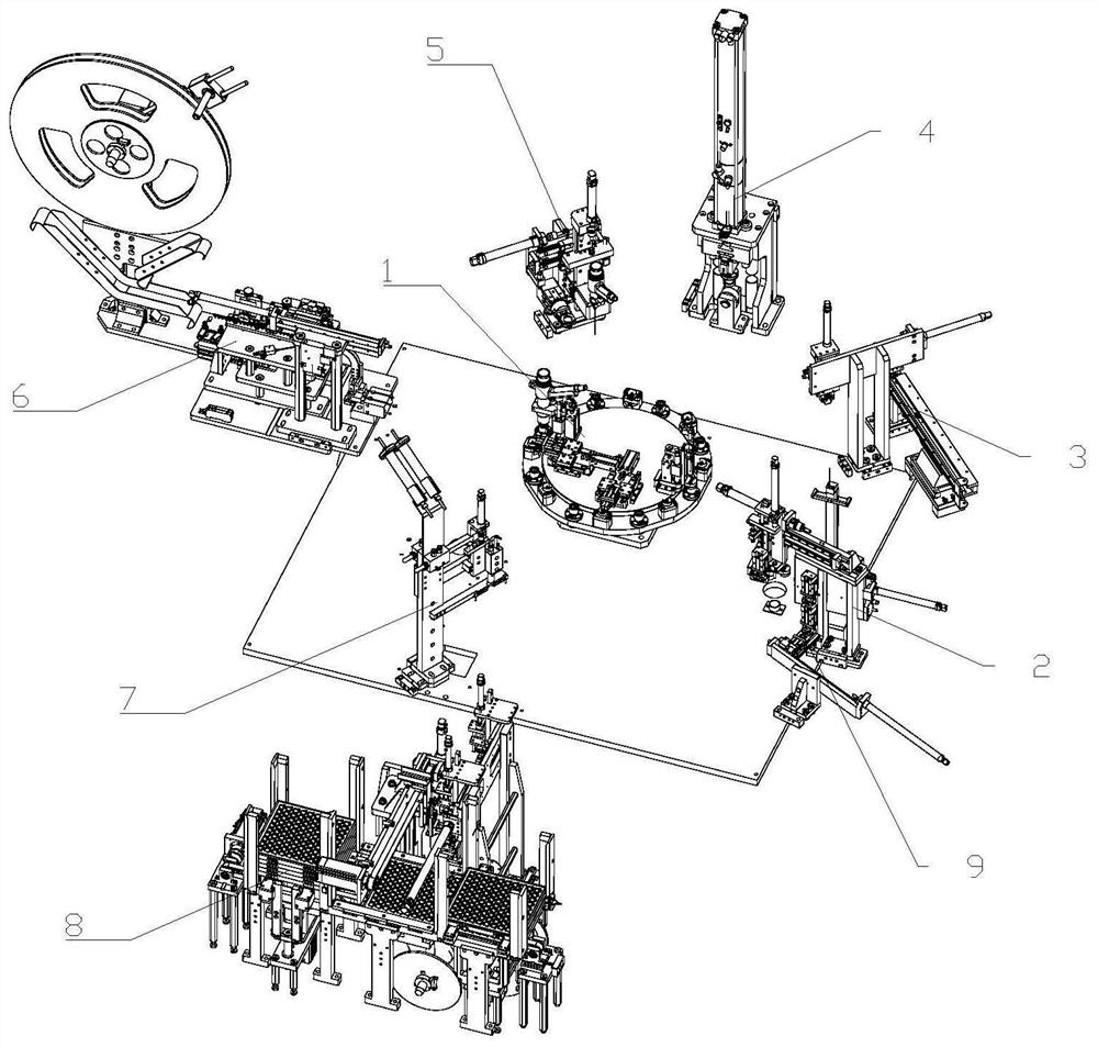
[0047] Such as figure 2 As shown, a permanent magnet DC motor assembly equipment includes a frame and a fixture rotating device 1 installed on the frame, a mandrel feeding device 2, a casing feeding device 3, a mandrel riveting device 4, a machine Shell turning device 5, shrapnel feeding device 6, mandrel oiling device 7, rotor feeding device 8 and product unloading device 9; the circumference of jig rotating device 1 is provided with a plurality of stations, which are respectively mandrel feeding station, casing loading station, riveting station, flipping station, shrapnel loading station, refueling station, rotor loading station and unloading station, the mandrel feeding device 2, The casing feeding device 3, the mandrel riveting device 4, the casing turning device 5, the shrapnel feeding device 6, the mandrel oiling device 7, the rotor feeding device 8 and the product unloading device 9 correspond to the jigs in sequence along the processing direction Rotate device 1 for ...


PUM


Abstract

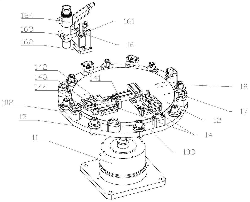
The invention relates to the field of motor production, in particular to a Jig rotating device and circulating method for a permanent magnet direct-current motor and motor assembling equipment. The jig rotating device for motor assembly production comprises a turntable, a fixed disc, a rotating disc, a clamping assembly, an air blowing assembly, a forward mounting jig and a reverse mounting jig, wherein the turntable is arranged on the rack; a fixed shaft and a rotating shaft are arranged at the upper end of the turntable; the center of the fixed disc is fixed on the fixed shaft;the rotating disc is mounted on the rotating shaft; and the fixed disc is positioned above the rotating disc; the forward mounting jig and the reverse mounting jig are mounted on the periphery of the clamping assembly mounted on the rotating disc; the clamping assembly is fixed on the disc; and the air blowing assembly is arranged on the fixed disc and corresponds to the reverse mounting jig at an elastic sheet feeding station. Two jigs are adopted, so that the jig rotating device has the advantages of being suitable for mandrel loading and high in loading precision.

Description

technical field [0001] The invention relates to the field of motor production, in particular to a fixture rotating device for a permanent magnet DC motor, a transfer method and motor assembly equipment. Background technique [0002] Motors are widely used in various portable electronic devices or appliances, such as tape recorders, VCD players, record players, electric massagers and various toys. Permanent magnet DC motors are a kind of DC motors that use permanent magnets to establish a magnetic field. The structure of the permanent magnet DC motor consists of a general stator and a rotor, and the stator includes a casing, magnetic tiles, magnetic tile frames, riveting parts, and the like. In the prior art, the stator assembly of the DC permanent magnet motor is generally done manually, such as Figure 22 The shown motor rotor consists of a casing (100), a mandrel (200), shrapnel (300) and a rotor (400). The mandrel (200) is fixed on the casing (100), the shrapnel (300) is...

Claims


Application Information

Patent Timeline
IPC IPC(8): B23P21/00B23P23/04B25B11/02H02K15/02H02K15/14B23P19/00B23P19/02
CPCB23P21/006B25B11/02B23P19/001B23P19/02H02K15/02H02K15/14B23P23/04
Inventor 陈荣乾朱在修陈开文吴志兵
Owner 陈荣乾
Learn More