
Positioning mechanism for precise gear hobbing machine and using method thereof

A technology of positioning mechanism and gear hobbing machine, which is applied in the direction of gear cutting machines, components with teeth, gear teeth, etc., can solve the problems of inaccurate positioning and increased work intensity of staff.

Pending Publication Date: 2021-09-14
江苏马步崎电机制造有限公司
View PDF0 Cites 0 Cited by
  • Summary
  • Abstract
  • Description
  • Claims
  • Application Information

AI Technical Summary

Problems solved by technology

[0004] The purpose of the present invention is to provide a positioning mechanism for a precision hobbing machine and its use method, to solve the problem that the existing positioning mechanism for a precision hobbing machine in the above-mentioned background technology often causes the staff to work due to inaccurate positioning during use. The problem of increased intensity

Method used


Image

  • Positioning mechanism for precise gear hobbing machine and using method thereof
  • Positioning mechanism for precise gear hobbing machine and using method thereof
  • Positioning mechanism for precise gear hobbing machine and using method thereof

Examples


Embodiment Construction

[0025] The following will clearly and completely describe the technical solutions in the embodiments of the present invention with reference to the accompanying drawings in the embodiments of the present invention. Obviously, the described embodiments are only some, not all, embodiments of the present invention.

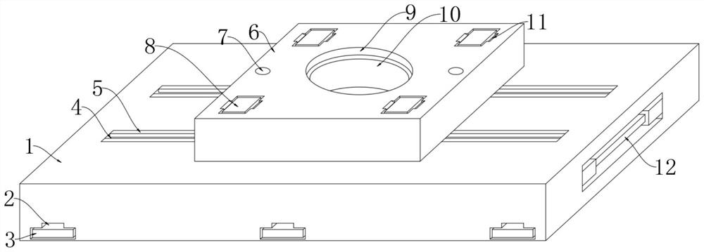
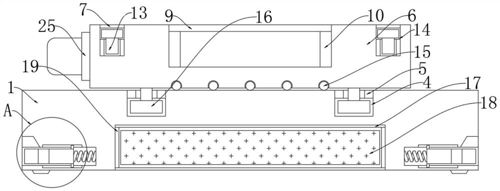
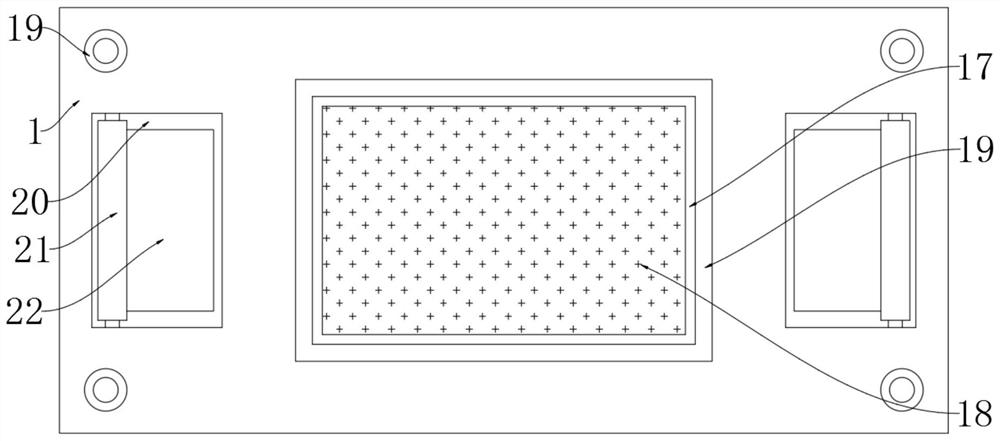
[0026] see Figure 1-5 , an embodiment provided by the present invention: a positioning mechanism for a precision hobbing machine, including a fixed horizontal plate 1, a movable upper block 6 is arranged above the fixed horizontal plate 1, and both ends of the upper movable block 6 are provided with Sensor placement groove 14, the inside of sensor placement groove 14 is provided with ranging sensor 13, and ranging sensor 13 is fixedly connected with movable upper block 6 by sensor holder, allows the connection between ranging sensor 13 and movable upper block 6 more firmly, The top of the ranging sensor 13 is provided with a block glass block 7, and the block glass ...


PUM


Abstract

The invention discloses a positioning mechanism for a precise gear hobbing machine and a using method thereof, relates to the technical field of auxiliary devices for positioning of precise gear hobbing machines, and aims to solve the problem that the working intensity of workers is increased due to the fact that an existing positioning mechanism for the precise gear hobbing machine is not accurate enough in positioning during use. A movable upper block is arranged above a fixed transverse plate block, sensor placing grooves are formed at the two ends of the upper portion of the movable upper block, distance measuring sensors are arranged in the sensor placing grooves, and the distance measuring sensors are fixedly connected with the movable upper block through sensor fixing bases; a blocking glass block is arranged above the distance measuring sensors and fixedly connected with the movable upper block, an audible and visual alarm is arranged at one end of the movable upper block and electrically connected with the distance measuring sensors, and an inner bearing placement groove is formed in the middle of the movable upper block; and an inner bearing is arranged in the inner bearing placement groove.

Description

technical field [0001] The invention relates to the technical field of an auxiliary device for positioning a precision hobbing machine, in particular to a positioning mechanism for a precision hobbing machine and a method for using the same. Background technique [0002] Precision hobbing machine is the most widely used machine tool in gear processing machine tools. It can cut straight teeth and helical cylindrical gears, and can also process worm gears and sprockets. And herringbone cylindrical gear and worm gear processing machine tool, this machine tool can also process various special tooth-shaped workpieces such as splines and sprockets when using a special hob, and it will be used when using a precision hobbing machine. Positioning mechanism of precision gear hobbing machine. [0003] The existing positioning mechanism for precision gear hobbing machine often has the problem of increased work intensity due to inaccurate positioning during use. To this end, we propose ...

Claims


Application Information

Patent Timeline
Patent Type & Authority Applications(China)
IPC IPC(8): B23F23/00B23Q1/00B23Q17/00
CPCB23F23/00B23Q1/00B23Q17/00
Inventor 章进平曹祯兴
Owner 江苏马步崎电机制造有限公司
Learn More