Soil improvement device
A technology of soil improvement and placing plates, which is applied in spraying devices, restoration of contaminated soil, shovels, etc. It can solve the problems of easy precipitation of drugs, poor quality of soil improvement, and uneven mixing of drugs, etc.
- Summary
- Abstract
- Description
- Claims
- Application Information
AI Technical Summary
Problems solved by technology
Method used
Image

Examples
Embodiment 1
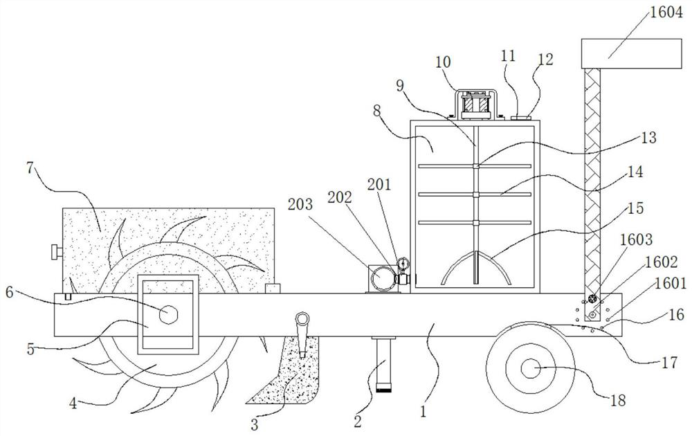
[0035] Example 1: See Figure 1-6 , a soil improvement device, comprising a placement board 1, one side of the bottom end of the placement board 1 is provided with an arc-shaped groove 17, the bottom end of the arc-shaped groove 17 is provided with a moving wheel 18, and the bottom end of the placement board 1 is provided with an auxiliary spraying device Structure 2, one end of the placement plate 1 is provided with a first drive motor 5, the model of the first drive motor 5 can be Y90L-2, the output end of the first drive motor 5 passes through the interior of one end of the placement plate 1 through the drive shaft and is fixed A shaft body 6 is connected, and the outside of the shaft body 6 is fixedly connected with a turning roller 4. The top of the turning roller 4 is provided with a protective structure 7, and the bottom end of the plate 1 on one side of the turning roller 4 is provided with an auxiliary collection structure 3. One side of the placing plate 1 is provide...
Embodiment 2
[0039] Embodiment 2: Auxiliary spraying structure 2 is made up of valve 201, connecting pipe 202, water storage tank 203, water distribution pipe 204, movable sleeve 205, spray hole 206 and screen 207, one side of connecting pipe 202 and one side of mixing box 8 The bottom end of the connecting pipe 202 is fixedly connected, the outside of the connecting pipe 202 is provided with a valve 201, one side of the connecting pipe 202 is fixedly connected with a water storage tank 203, the bottom end of the water storage tank 203 is fixedly connected with a water distribution pipe 204, and the bottom end of the water distribution pipe 204 is provided with Spray hole 206, movable sleeve 205 is arranged on the outside of the bottom end of water distribution pipe 204, and the bottom end of movable sleeve 205 is fixedly connected with screen 207, and the bottom end of water distribution pipe 204 runs through the inside of placement plate 1 longitudinally, and connects one side of pipe 202 ...
Embodiment 3
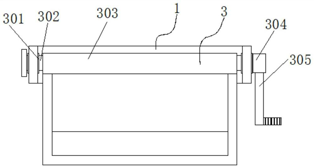
[0042] Embodiment 3: The auxiliary collection structure 3 is composed of a movable groove 301, a movable shaft 302, a collection frame 303, a fixed sleeve 304, and a handle 305. The movable groove 301 is arranged at both ends of the auxiliary collection structure 3, and the movable grooves 301 penetrate horizontally. A movable shaft 302 is provided, and the outer part of the movable shaft 302 is fixedly connected with a collection frame 303, and the outer part of one end of the movable shaft 302 is fixedly connected with a fixed sleeve 304, and the bottom end of the fixed sleeve 304 is fixedly connected with a handle 305;
[0043] Both ends of the movable shaft 302 are embedded in the movable groove 301, and the collecting frame 303 forms a rotating structure through the fixed sleeve 304 and the movable groove 301;
[0044] Specifically, such as figure 1 and image 3 Shown, utilize collecting frame 303, can the soil of soil turning roller 4 in the soil-turning process be coll...
PUM
 Abstract
Description
Claims
Application Information
 - Generate Ideas
- Intellectual Property
- Life Sciences
- Materials
- Tech Scout
- Unparalleled Data Quality
- Higher Quality Content
- 60% Fewer Hallucinations
Browse by: Latest US Patents, China's latest patents, Technical Efficacy Thesaurus, Application Domain, Technology Topic, Popular Technical Reports.
© 2025 PatSnap. All rights reserved.Legal|Privacy policy|Modern Slavery Act Transparency Statement|Sitemap|About US| Contact US: help@patsnap.com