Permanent magnet motor assembling mould

A technology of permanent magnet motor and mould, applied in the field of machinery, can solve problems such as parts and insulation damage, affecting the quality of the motor, etc.

Pending Publication Date: 2021-09-10
FUSHUN COAL MINE MOTOR MFG
View PDF0 Cites 0 Cited by
  • Summary
  • Abstract
  • Description
  • Claims
  • Application Information

AI Technical Summary

Problems solved by technology

The assembly process often causes damage to parts and insulation, affecting the quality of the motor

Method used


Image

  • Permanent magnet motor assembling mould
  • Permanent magnet motor assembling mould
  • Permanent magnet motor assembling mould

Examples


Embodiment Construction

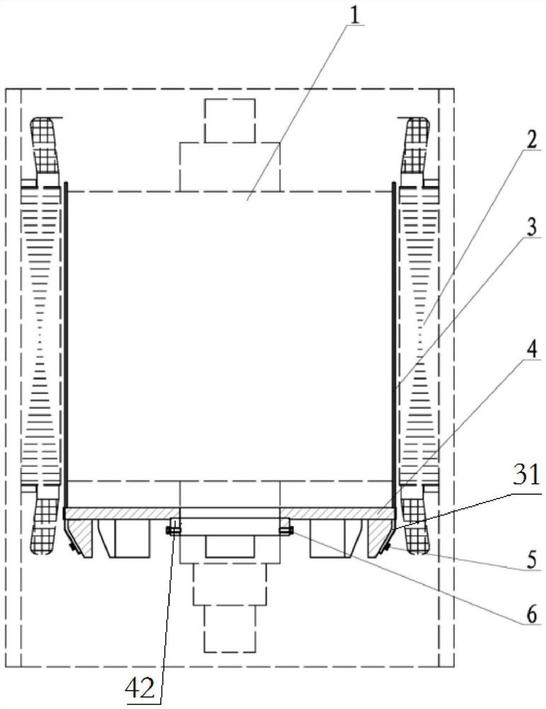
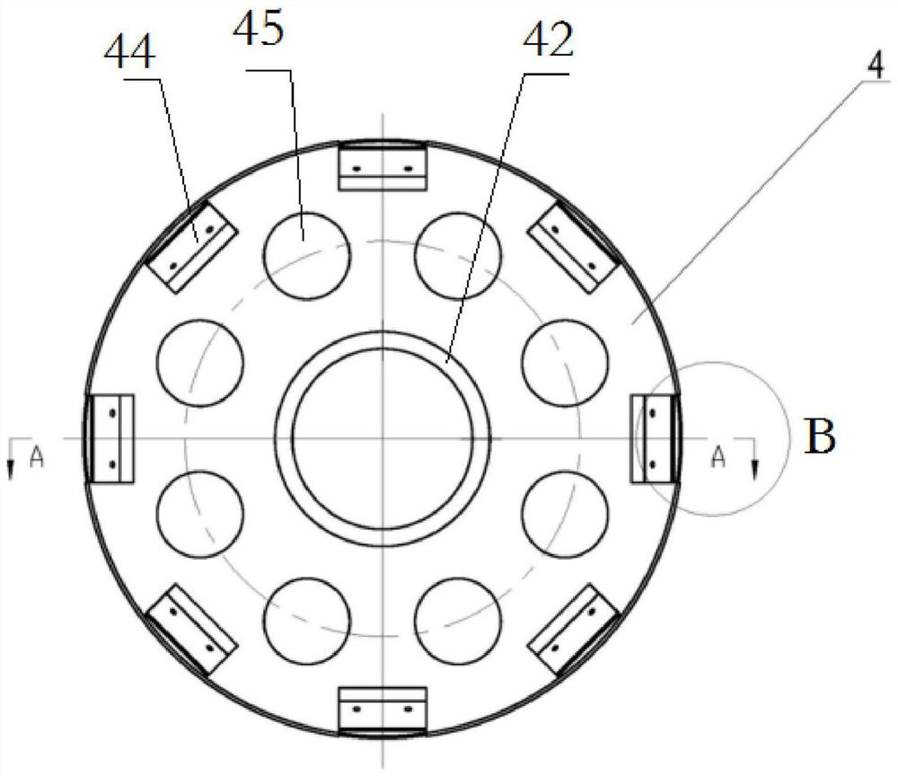
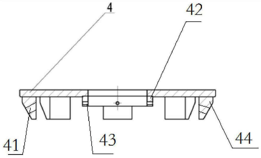
[0016] The present invention will be described in detail below in conjunction with the accompanying drawings. As shown in the figure, the present invention includes a disc-shaped base 4, the upper end of the base abuts against the axial end of the rotor 1, and the lower end of the base 4 is provided with a limit ring 42, so that A radial screw hole 43 is set on the limit ring 42, the front end of the main shaft of the rotor passes through the limit ring 42 and is locked by the first positioning screw 6 tightened on the limit ring; the outer ring of the lower end of the base is provided with multiple A positioning post 44, screw holes 41 are set on the positioning post, and through holes are set at the lower end of the magnetic separation strip 3, and the second positioning screw 5 is screwed on the positioning post 44 after passing through the through hole; the upper end of the magnetic separation strip Fit snugly on the outside of the rotor. When in use, in order to prevent t...


PUM


Abstract

The invention discloses a permanent magnet motor assembling mould. The permanent magnet motor assembling mould comprises a disc-shaped base, the upper end of the base abuts against the axial end of a rotor, a limiting ring is arranged at the lower end of the base, a radial screw hole is formed in the limiting ring, and the front end of a main shaft of the rotor penetrates through the limiting ring and is locked by a first positioning screw screwed on the limiting ring; a plurality of positioning columns are arranged on the outer ring of the lower end of the base, screw holes are formed in the positioning columns, through holes are formed in the lower ends of the magnetic isolation strips, and second positioning screws penetrate through the through holes and then are screwed on the positioning columns; and the upper ends of the magnetic isolation strips are tightly attached to the outer side of the rotor. The permanent magnet motor assembling mould has the advantages that the rotor and the mould are fixed by using the first positioning screw, then the magnetic isolation strip made of a white steel plate is assembled with the mould and fixed by using the bolt and the second positioning screw to form an assembly, the assembly is assembled with the stator, and the mould and the magnetic isolation strip are taken out after the assembly is completed, so that the influence of strong magnetism on the assembly of the permanent magnet motor is solved; and the product quality is improved.

Description

technical field [0001] The invention relates to the field of machinery, in particular to an assembly mold for a motor. Background technique [0002] Because the permanent magnet motor rotor is equipped with magnetic steel inside, it has strong magnetism. During assembly, the rotor and the stator are adsorbed together, so that the assembly cannot be continued. It is necessary to apply pressure with a press to install the rotor in place. During this process, the inner and outer diameters of the stator and rotor will rub against each other, and then use the cooperation between the end cover and the bearing to separate the stator and rotor. Create an air gap. The assembly process often causes damage to parts and insulation, affecting the quality of the motor. Contents of the invention [0003] In order to solve the above technical problems, the object of the present invention is to provide a permanent magnet motor assembly mold, including a disc-shaped base, the upper end of...

Claims


Application Information

Patent Timeline
Patent Type & Authority Applications(China)
IPC IPC(8): H02K15/16H02K15/03
CPCH02K15/16H02K15/03
Inventor 王洪久曹建春李微张思思李洪生
Owner FUSHUN COAL MINE MOTOR MFG
Why Eureka
Try Eureka