Laser base and laser

A laser and base technology, applied in semiconductor laser optics, lasers, laser parts, etc., can solve problems such as low efficiency and difficult coupling

Pending Publication Date: 2021-09-10
芯峰光电技术(深圳)有限公司
View PDF0 Cites 0 Cited by
  • Summary
  • Abstract
  • Description
  • Claims
  • Application Information

AI Technical Summary

Problems solved by technology

The second is the problem of low efficiency caused by the difficulty of coupling caused by the spatial coupling mode

Method used


Image

  • Laser base and laser
  • Laser base and laser
  • Laser base and laser

Examples


Embodiment Construction

[0031] In order to facilitate the understanding of the present invention, the present invention will be described more fully below with reference to the associated drawings. Preferred embodiments of the invention are shown in the accompanying drawings. However, the present invention can be embodied in many different forms and is not limited to the embodiments described herein. On the contrary, the purpose of providing these embodiments is to make the disclosure of the present invention more thorough and comprehensive.

[0032] Unless otherwise defined, all technical and scientific terms used herein have the same meaning as commonly understood by one of ordinary skill in the technical field of the invention. The terminology used herein in the description of the present invention is only for the purpose of describing specific embodiments, and is not intended to limit the present invention.

[0033] With the development of the optical communication industry, the commonly used t...


PUM


Abstract

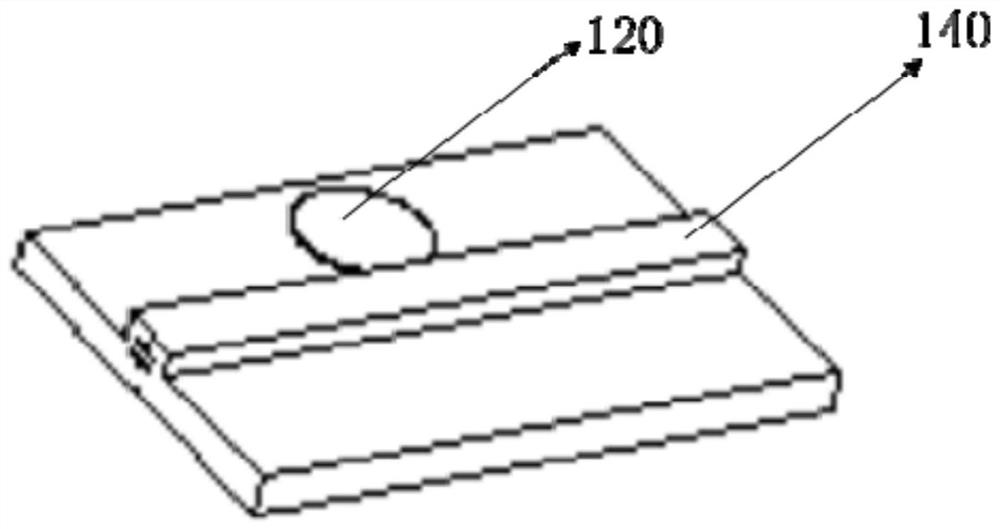
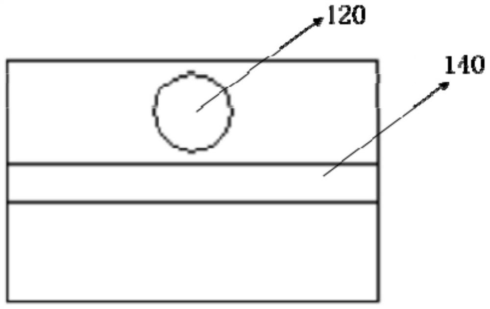
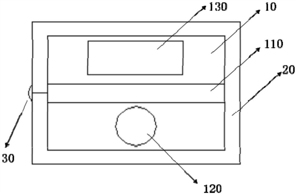
The invention provides a laser base and a laser. The laser base comprises a substrate with two opposite surfaces, a baffle and a lens, wherein the baffle is arranged on the first surface, the substrate and the baffle are connected to form a containing cavity, and the containing cavity is used for containing a laser chip; a strip-shaped waveguide structure is arranged on the first surface, and a strip-shaped bulge is arranged on the second surface; a light outlet hole is formed in the end part of the strip-shaped bulge or in the position, corresponding to the strip-shaped waveguide structure, of the baffle; the lens is arranged at the light outlet hole; the strip-shaped waveguide structure is configured to guide light rays; the lens is configured to collimate light rays radiated by the laser chip or narrow the divergence angle of the light rays; or the lens is configured to focus the light incident from the outside. On one hand, coupling of the optical waveguide and the lens is achieved, on the other hand, collimation or divergence angle narrowing of radiation light of the laser emitting chip is achieved, and convergence of external incident light is achieved.

Description

technical field [0001] The invention relates to the technical field of laser packaging, in particular to a laser base and a laser. Background technique [0002] With the development of the optical communication industry, the commonly used transmitter optical sub-assembly (TOSA) and receiver optical sub-assembly (ROSA) have formed some relatively standardized packages, such as TO-CAN package and BOX hermetic package. The TO-CAN package is shaped like a cylindrical jar, consisting of a shell cap and a shell seat. The BOX hermetic packaging is mainly used for the packaging of high-speed optical devices for medium and long-distance transmission, so as to meet the requirements of long-term service life of the device. [0003] However, whether it is the aforementioned TO-CAN package or the BOX hermetic package, the coupling efficiency of the lens part in the component is very low. Taking a spherical lens as an example, the coupling efficiency of a ball with a slightly larger dia...

Claims


Application Information

Patent Timeline
Patent Type & Authority Applications(China)
IPC IPC(8): H01S5/02253H01S5/02315H01S5/06H01S5/22H01S5/00
CPCH01S5/22H01S5/06H01S5/0085H01S5/005H01S5/02253H01S5/02315
Inventor 钟文彪钟文斌
Owner 芯峰光电技术(深圳)有限公司
Why Eureka
Try Eureka