
Energy storage battery cluster with simplified structure

An energy storage battery, a technology with simplified structure, applied in the direction of secondary batteries, structural parts, battery pack components, etc., can solve the problems of difficult maintenance, heavy weight, and complicated assembly.

Pending Publication Date: 2021-09-10
SHANGHAI YUYUAN POWER TECH CO LTD
View PDF5 Cites 1 Cited by
  • Summary
  • Abstract
  • Description
  • Claims
  • Application Information

AI Technical Summary

Problems solved by technology

At present, in the field of new energy vehicles, the method used to increase energy density and reduce costs is demodularization (CTP technology), but this technology cannot be copied and applied to the field of energy storage. Most of the energy storage field still uses traditional battery-battery modules. -Composite design of battery pack-battery cluster
[0004] In the existing technical solutions, since the energy storage system does not have a chassis similar to that of new energy vehicles that can carry battery packs or modules, the integrated chassis technology of new energy vehicles is not applicable
Energy storage systems using traditional technical solutions have a series of problems such as complex assembly, low energy storage per unit volume, heavy weight (the container needs to be used as a load-bearing foundation), and difficult maintenance.

Method used


Image

  • Energy storage battery cluster with simplified structure
  • Energy storage battery cluster with simplified structure
  • Energy storage battery cluster with simplified structure

Examples


Embodiment Construction

[0025] In order to make the technical means, creative features, goals and effects achieved by the present invention easy to understand, the present invention will be further described below in conjunction with specific embodiments.

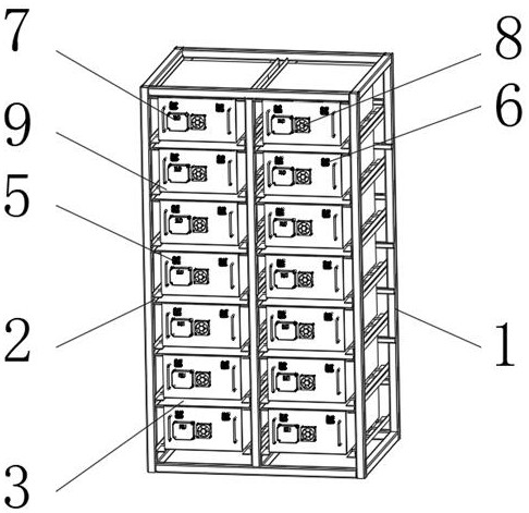
[0026] Such as Figure 1-5 As shown, an energy storage battery cluster with a simplified structure includes a battery frame 1, battery modules and battery module engaging grooves 2 are provided on both inner surfaces of the battery frame 1, and battery module engagement grooves 2 are provided between the inner surfaces on both sides of the battery frame 1. The battery module layer support 3 is provided with a battery cluster body 9 on the outer surface of the upper end of the battery module layer support 3 , and a lithium ion battery 4 is disposed inside the battery cluster body 9 .

[0027] The battery cluster body 9 includes a bottom plate 901, side plates 902 are fixedly installed on both sides of the bottom plate 901, a rear end plate 903 is f...


PUM


Abstract

The invention discloses an energy storage battery cluster with a simplified structure, which comprises a battery rack, the inner surfaces of the two sides of the battery rack are provided with battery modules and battery module occlusion grooves, a battery module layer support is arranged between the inner surfaces of the two sides of the battery rack, and the outer surface of the upper end of the battery module layer support is provided with a battery cluster body. According to the energy storage battery cluster with the simplified structure, after the lithium batteries form the module, the module is directly installed on the battery rack of the battery cluster, the weight of the module is directly borne by the reinforcing beams of the battery rack, and a bottom shell in a traditional method is omitted. Occlusion structures are arranged between the modules as well as between the modules and the battery rack, so that the structure is stable, and easy dislocation caused by shaking or external impact is avoided. Due to the fact that no closed pack shell is arranged outside the module, the heat dissipation area of the module is increased, and the heat dissipation efficiency is higher. A large module structure is adopted, the structure is simplified, meanwhile, the material cost and the manufacturing cost are reduced, and meanwhile installation and maintenance are convenient.

Description

technical field [0001] The invention relates to the technical field of batteries, in particular to a structurally simplified energy storage battery cluster. Background technique [0002] At present, in the field of large-scale energy storage of lithium-ion batteries, lithium battery cells are basically combined into modules in series and parallel, and then the modules are assembled into battery packs in series or in parallel, and the battery packs are then assembled into battery packs through The battery clusters are formed in series and parallel, and then multiple battery clusters are fixed in the container to form a large-scale energy storage system. Since battery modules and battery packs require a large amount of structural materials, the weight of the entire energy storage system is increased. The production cycle of battery modules and battery packs is long and the process is complex, which also reduces the production efficiency of the entire energy storage system, in...

Claims


Application Information

Patent Timeline
IPC IPC(8): H01M50/204H01M50/209H01M50/242H01M50/233H01M50/258H01M50/244H01M50/264H01M50/24H01M10/613H01M10/0525
CPCH01M50/204H01M50/209H01M50/242H01M50/233H01M50/258H01M50/244H01M50/264H01M50/24H01M10/613H01M10/0525Y02E60/10
Inventor 尚德华杨泽乾
Owner SHANGHAI YUYUAN POWER TECH CO LTD
Learn More