
Electromagnetic relay with button buffer mechanism

A technology of electromagnetic relay and buffer mechanism, applied in the direction of electromagnetic relay, electromagnetic relay details, relay, etc., can solve the problems of broken damage, no buffer function, affecting the normal operation of electromagnetic relay, etc.

Pending Publication Date: 2021-09-10
宁波金海电子有限公司
View PDF0 Cites 1 Cited by
  • Summary
  • Abstract
  • Description
  • Claims
  • Application Information

AI Technical Summary

Problems solved by technology

[0002] The electromagnetic relay mainly includes a shell, a contact system, a magnetic circuit system, etc. There is an armature connected between the magnetic circuit systems. After the magnetic circuit system is energized, the iron core in it will be attracted to the armature to realize the conduction of the internal circuit of the electromagnetic relay. A button that is in movable contact with the armature is often installed on the shell corresponding to the armature. The button of the electromagnetic relay is a switch for the debugger to detect whether the load end circuit of the relay is normal, but the button in the prior art is a solid structure without buffering Function, when the button is subjected to external force, the button is directly in conflict with the armature rigidity, at this time, a large reverse pressure is often generated to act on the button, because the material of the button is mostly hard plastic, so the bending part of the button is very easy Due to excessive concentrated pressure, it is broken and damaged, which makes the detection function of the electromagnetic relay circuit on and off invalid, seriously affecting the normal operation of the electromagnetic relay

Method used


Image

  • Electromagnetic relay with button buffer mechanism
  • Electromagnetic relay with button buffer mechanism
  • Electromagnetic relay with button buffer mechanism

Examples


Embodiment Construction

[0041] To further illustrate the various embodiments, the present invention is provided with accompanying drawings. These drawings are a part of the disclosure of the present invention, which are mainly used to illustrate the embodiments, and can be combined with related descriptions in the specification to explain the operating principles of the embodiments. With reference to these contents, those skilled in the art should understand other possible implementations and advantages of the present invention. Components in the figures are not drawn to scale, and similar component symbols are generally used to denote similar components.

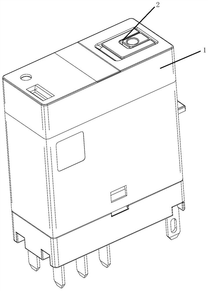
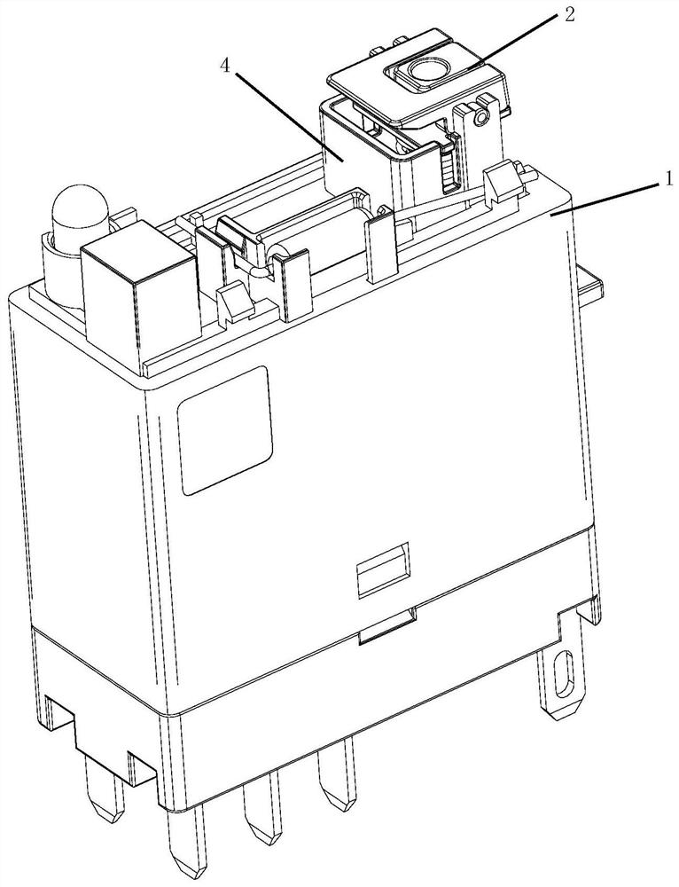
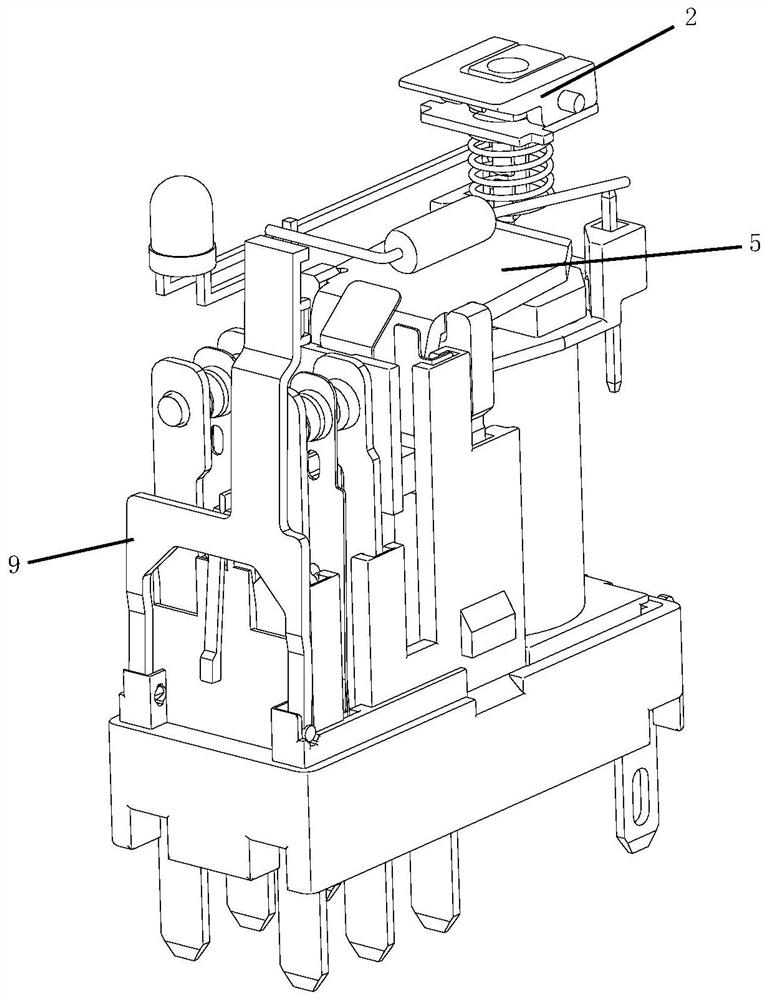
[0042] refer to Figure 1-8 As shown, as a preferred embodiment of the present invention, an electromagnetic relay with a button buffer mechanism is provided, including a housing 1, a button 2 assembly and a contact system located in the housing 1, and the housing 1 is provided with a mounting The mounting seat of the button 2 assembly, the butt...


PUM


Abstract

The invention relates to the technical field of relays, and particularly relates to an electromagnetic relay with a button buffer mechanism. The electromagnetic relay comprises a shell, a button assembly and a contact system positioned in the shell, the shell is provided with a mounting seat for mounting the button assembly, the button assembly comprises a button and an elastic piece matched with the button, the bottom of the button is provided with a buffer key rod, and the buffer key rod can extend into the shell to be in movable contact with an armature so that a contact system is connected or disconnected, and the test work of a load end circuit of the electromagnetic relay is completed. The buffer key rod is provided with an action end which is in contact with the armature so that the buffer key rod can buffer and disperse the pressure generated by the action end and the armature which are pressed against each other. And the failure of the detection function of the on-off of the circuit of the electromagnetic relay caused by the breakage of the button due to overlarge and concentrated pressure is prevented.

Description

technical field [0001] The invention relates to the technical field of relays, in particular to an electromagnetic relay with a button buffer mechanism. Background technique [0002] The electromagnetic relay mainly includes a shell, a contact system, a magnetic circuit system, etc. There is an armature connected between the magnetic circuit systems. After the magnetic circuit system is energized, the iron core in it will be attracted to the armature to realize the conduction of the internal circuit of the electromagnetic relay. A button that is in movable contact with the armature is often installed on the shell corresponding to the armature. The button of the electromagnetic relay is a switch for the debugger to detect whether the load end circuit of the relay is normal, but the button in the prior art is a solid structure without buffering Function, when the button is subjected to external force, the button is directly in conflict with the armature rigidity, at this time,...

Claims


Application Information

Patent Timeline
IPC IPC(8): H01H50/02H01H13/14H01H13/20
CPCH01H50/02H01H13/14H01H13/20
Inventor 林永斌黄诚
Owner 宁波金海电子有限公司
Learn More