Centripetal force experimental device
An experimental device and technology of centripetal force, applied in the direction of educational appliances, instruments, teaching models, etc., can solve problems such as large errors, unintuitive centripetal force demonstration experiments, and inability to obtain experimental data
- Summary
- Abstract
- Description
- Claims
- Application Information
AI Technical Summary
Problems solved by technology
Method used
Image
Examples
Embodiment 1
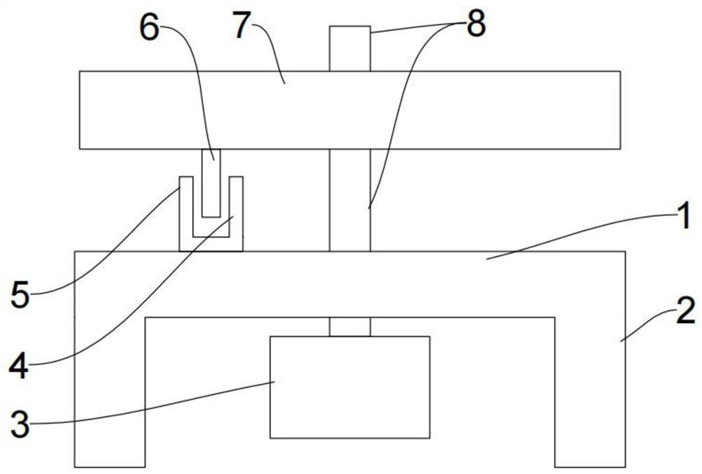
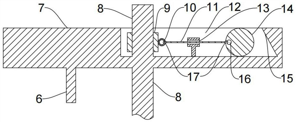
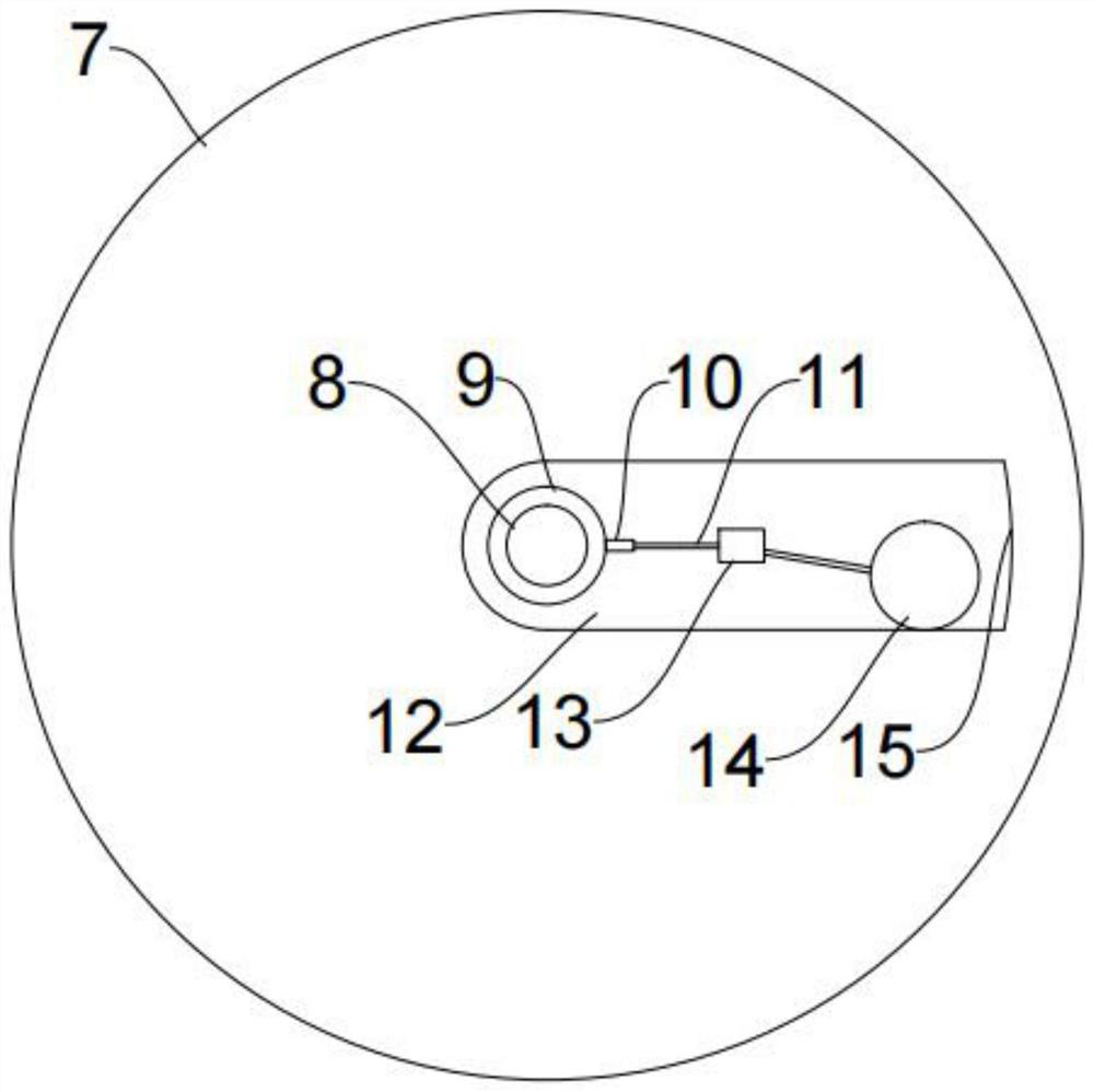
[0040] For ease of understanding, see Figure 1 to Figure 5 , an embodiment of a centripetal force experimental device provided by the present application, including a base 1, a turntable 7, a controller, a rotating motor 3, a photoelectric gate, a tension sensor 9, a pressure sensor, several spheres 14 with different masses but the same size, A number of flexible ropes 11 with different lengths and no elasticity.
[0041] The turntable 7 is located above the base 1, and the rotary motor 3 is arranged below the base 1. The center of the turntable 7 is provided with a central shaft 8 that runs through the turntable 7 vertically. The central shaft 8 passes through the top of the base 1 and is connected to the rotating shaft of the rotary motor 3. 3 is used for driving turntable 7 to rotate.
[0042] The upper surface of the rotating disk 7 is provided with a limiting groove 12 connected to the center of the rotating disk 7. The limiting groove 12 is used to limit the ball 14 to r...
Embodiment 2
[0054] For ease of understanding, see Figure 1 to Figure 5 , this embodiment is a further improvement of the centripetal force experimental device provided in embodiment 1, the depth of the limiting groove 12 is greater than the radius of the sphere 14 .
[0055] The limit groove 12 is connected from the edge of the turntable 7 to the center, and the end of the limit groove 12 away from the center of the turntable 7 is provided with a baffle plate 15 for preventing the ball 14 from flying out.
[0056] The side of the baffle plate 15 close to the center of the turntable 7 is provided with a rubber layer.
[0057] The upper end of the baffle plate 15 is inclined towards the center of the rotating disk 7 .
[0058] It should be noted that the center of gravity of the sphere 14 is located at the center of the sphere, and the depth of the limiting groove 12 is set to be greater than the radius of the sphere 14 so that the sphere 14 is not easy to roll out of the limiting groove ...
Embodiment 3
[0060] For ease of understanding, see Figure 1 to Figure 5 , this embodiment is a further improvement of the centripetal force experimental device provided in embodiment 1, and a transparent protective cover for covering the turntable 7 is provided above the base 1 .
[0061] The ball 14 is provided with a through hole 16 , and the flexible rope 11 passes through the through hole 16 to connect with the ball 14 .
[0062] Buckles 17 are provided at both ends of the flexible rope 11 , and the flexible rope 11 is respectively connected to the pull ring 10 and the through hole 16 through the buckles 17 .
[0063] The base 1 is provided with height-adjustable support feet 2 .
[0064] There is a rubber layer at the bottom of the support foot 2
[0065] It should be noted that the protective cover plays the role of protecting the turntable 7, and can also prevent the ball 14 from flying out during the test. The flexible rope 11 is connected to the sphere 14 through the through h...
PUM
 Abstract
Description
Claims
Application Information
 - R&D
- Intellectual Property
- Life Sciences
- Materials
- Tech Scout
- Unparalleled Data Quality
- Higher Quality Content
- 60% Fewer Hallucinations
Browse by: Latest US Patents, China's latest patents, Technical Efficacy Thesaurus, Application Domain, Technology Topic, Popular Technical Reports.
© 2025 PatSnap. All rights reserved.Legal|Privacy policy|Modern Slavery Act Transparency Statement|Sitemap|About US| Contact US: help@patsnap.com


