Mountain disaster monitoring terminal, mountain disaster self-adaptive monitoring and early warning method and debris flow/landslide self-adaptive monitoring and early warning method
A technology for monitoring terminal and mountain disasters, applied in geophysical survey, seismology, alarms, etc., can solve problems such as inability to provide clear and effective images, missing disaster information, and inability to meet early warnings.
- Summary
- Abstract
- Description
- Claims
- Application Information
AI Technical Summary
Problems solved by technology
Method used
Image
Examples
Embodiment 1
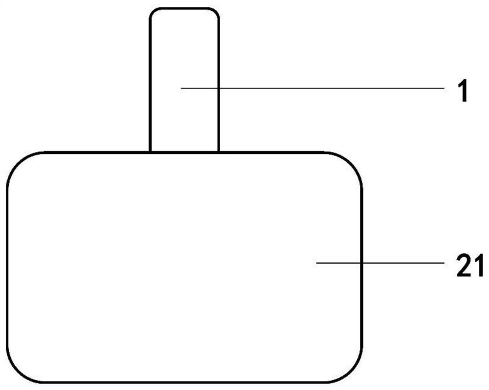
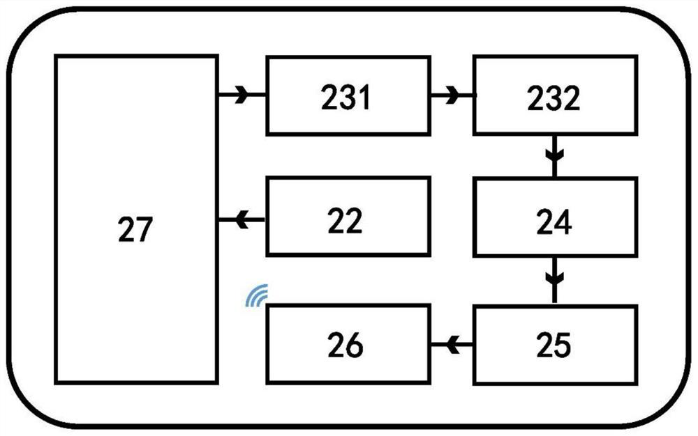
[0070] Such as Figure 1 ~ Figure 2 As shown, a mountain disaster monitoring terminal is processed.
[0071] figure 1 It is a schematic diagram of the external structure of the mountain disaster monitoring terminal. The mountain disaster monitoring terminal includes a rainfall sensor 1 and a data signal processing component 2. The outermost part of the data signal processing component 2 is a protection box 21, and inside the protection box 21 are other electronic components of the data signal processing component 2. The appearance of the mountain disaster monitoring terminal is an up-and-down structure, and the rain sensor 1 is fixedly connected to the outer surface of the upper part of the protection box 21 .
[0072] figure 2 It is a schematic diagram of the electronic component code of the data signal processing component. There are in the protection box 21: the rainfall monitoring assembly 22 connected with the rainfall sensor 1 signal, the earthquake signal detection...
Embodiment 2
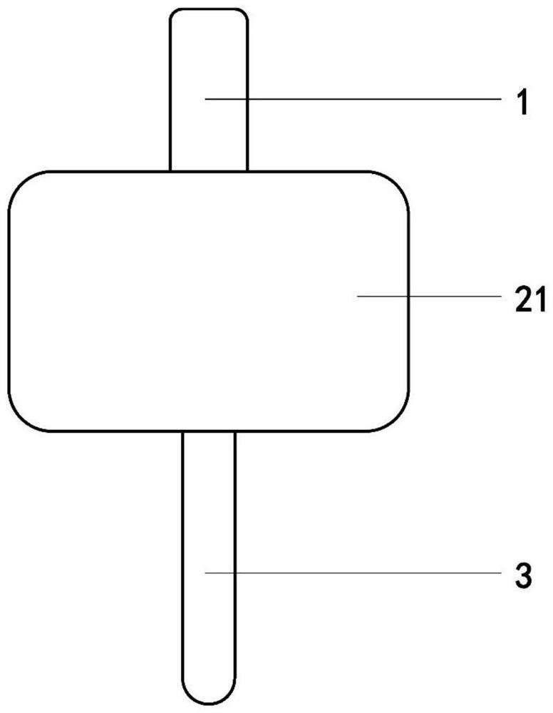
[0075] Such as image 3 As shown, a mountain disaster monitoring terminal is processed. The same parts as the first embodiment will not be repeated, and the difference lies in the addition of a ground motion transmission member 3 .
[0076] image 3 It is a schematic diagram of the external structure of the mountain disaster monitoring terminal (rod-shaped earthquake motion transmission part). The mountain disaster monitoring terminal also includes an earthquake transmission part 3 connected to the outer surface of the protection box 21 . The product as a whole has an upper, middle and lower structure. The rain sensor 1 is fixed above the outside of the protection box 21, and the seismic transmission part 3 is fixed below the outside of the protection box 21. Earthquake transmission part 3 is a solid bar-shaped part, which is detachably statically connected with the lower surface of protection box 21 .
Embodiment 3
[0078] Such as Figure 4 ~ Figure 5c As shown, a mountain disaster monitoring terminal is processed. Its similarity with Embodiment 2 will not be repeated, and its difference lies in the structure of the seismic vibration transmission part.
[0079] Figure 4 It is a schematic diagram of the external structure of the mountain disaster monitoring terminal (radiation symmetrical conical earthquake motion transmission part). The earthquake transmission part 3 is a radially symmetrical conical part, the big end is fixedly connected with the bottom surface of the protection box 21, and the small end is a free end. The seismic transmission part 3 is a solid metal part, and is detachably statically connected with the lower surface of the protection box 21 . Specifically, the top screw 32 of the vibration transmission part 3 may be connected with the threaded hole in the center of the lower surface of the protection box 21 .
[0080] Figure 5a It is a structural schematic diagra...
PUM
 Abstract
Description
Claims
Application Information
 - R&D Engineer
- R&D Manager
- IP Professional
- Industry Leading Data Capabilities
- Powerful AI technology
- Patent DNA Extraction
Browse by: Latest US Patents, China's latest patents, Technical Efficacy Thesaurus, Application Domain, Technology Topic, Popular Technical Reports.
© 2024 PatSnap. All rights reserved.Legal|Privacy policy|Modern Slavery Act Transparency Statement|Sitemap|About US| Contact US: help@patsnap.com


