
Lens structure, camera module and electronic equipment

A camera module and lens technology, applied in the field of photography, can solve the problems of lack of material, easy scratches, affecting the yield rate of lens structure, etc.

Pending Publication Date: 2021-09-10
JIANGXI JINGCHAO OPTICAL CO LTD
View PDF0 Cites 2 Cited by
  • Summary
  • Abstract
  • Description
  • Claims
  • Application Information

AI Technical Summary

Problems solved by technology

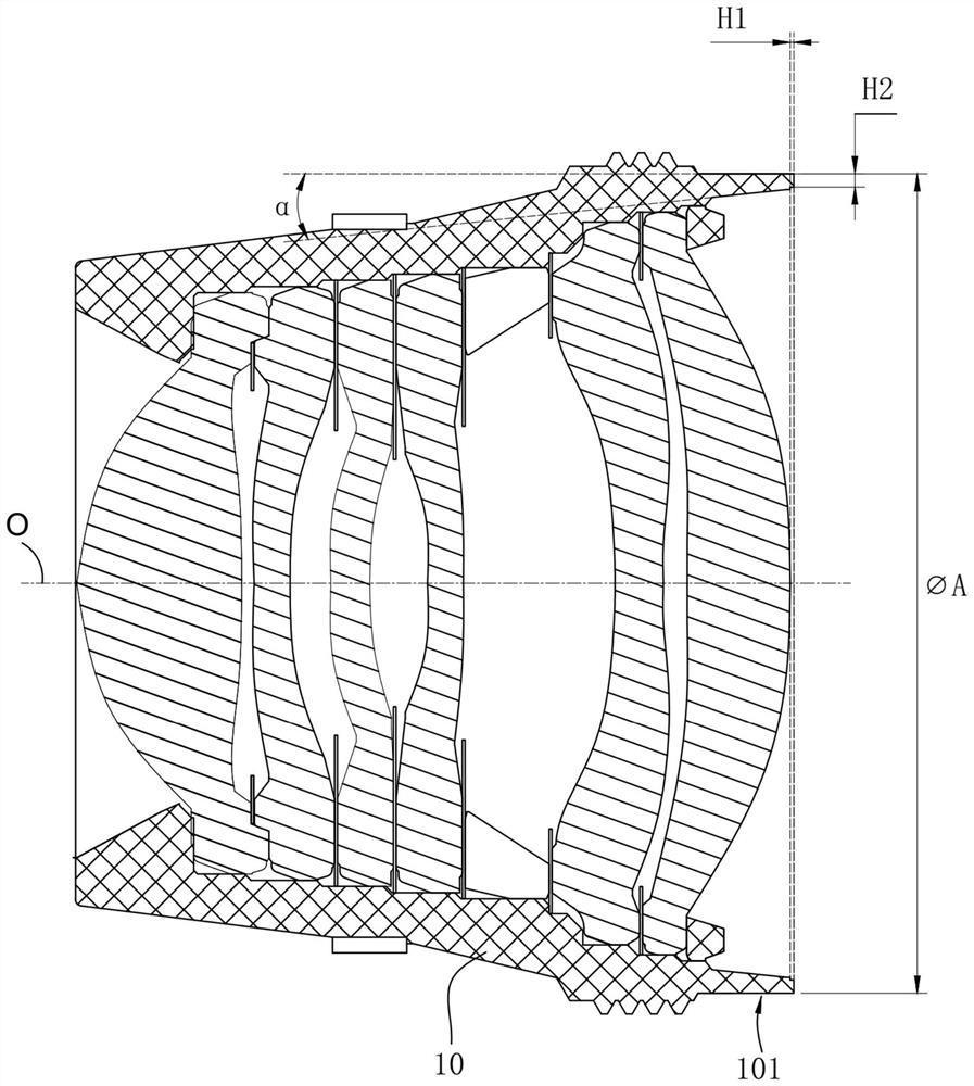
However, if the thickness H2 of the image-side end of the lens barrel is controlled within a relatively small range, the image-side end of the lens barrel will have the risk of material shortage and rupture, and the lens barrel will also be strained when the lens barrel is molded and demolded The risk of affecting the forming of the lens barrel; and if in order to ensure the forming of the lens barrel, it is generally necessary to control the thickness H2 of the image side end of the lens barrel within a relatively large range, which will cause the optical lens to protrude outside the lens barrel. The optical lens is easy to be scratched and dirty during subsequent production, which affects the yield rate of the lens structure

Method used


Image

  • Lens structure, camera module and electronic equipment
  • Lens structure, camera module and electronic equipment
  • Lens structure, camera module and electronic equipment

Examples


Embodiment Construction

[0049] The following will clearly and completely describe the technical solutions in the embodiments of the present invention with reference to the accompanying drawings in the embodiments of the present invention. Obviously, the described embodiments are only some of the embodiments of the present invention, not all of them. Based on the embodiments of the present invention, all other embodiments obtained by persons of ordinary skill in the art without making creative efforts belong to the protection scope of the present invention.

[0050] In the present invention, the terms "upper", "lower", "left", "right", "front", "rear", "top", "bottom", "inner", "outer", "middle", The orientations or positional relationships indicated by "vertical", "horizontal", "horizontal", and "longitudinal" are based on the orientations or positional relationships shown in the drawings. These terms are mainly used to better describe the present invention and its embodiments, and are not intended t...


PUM

PropertyMeasurementUnit
Thicknessaaaaaaaaaa

Abstract

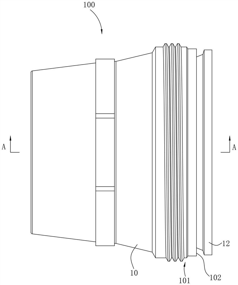
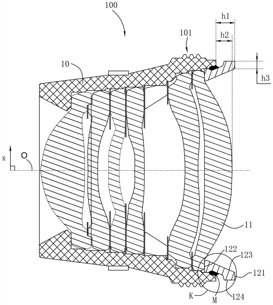
The invention discloses a lens structure, a camera module and electronic equipment, the lens structure comprises a lens cone, an optical lens and a compression ring, the optical lens is arranged in the lens cone, the compression ring is arranged at the image side end of the lens cone and extends out of the lens cone from the inside of the lens cone, and the first end face of the compression ring is located outside the lens cone, in the optical axis direction, the distance between the first end face and the image side face of the lens barrel is larger than the distance between the point, farthest from the object side face of the lens barrel, of the optical lens and the image side face of the lens barrel, the second end face of the pressing ring is located in the lens barrel and is opposite to the first end face, the inner circumferential face of the pressing ring is a conical face arranged around the optical axis, the inner diameter of the compression ring is gradually increased in the direction from the object side end of the lens barrel to the image side end of the lens barrel, and a first chamfer is arranged at the joint of the inner circumferential surface and the second end surface. By adopting the scheme, the optical lens can be prevented from protruding out of the pressing ring while the stable forming of the lens cone is ensured, and the pressing ring is used for protecting the optical lens, so that the risks of scratching and polluting the optical lens are reduced; and the imaging quality can be improved.

Description

technical field [0001] The invention relates to the field of camera technology, in particular to a lens structure, camera module and electronic equipment. Background technique [0002] Such as figure 1 As shown, in the related art, if the diameter of the image-side end of the lens barrel If it is too large, it is easy to interfere with the motor or base structure and affect the assembly. Therefore, the diameter of the image side end of the lens barrel Generally not too large. In order to prevent the optical lens from protruding out of the lens barrel (that is, H1>0mm, where H1 refers to the distance from the most protruding position on the optical lens to the outer end surface of the lens barrel), it is usually necessary to make the image of the lens barrel The angle α between the outer peripheral surface and the inner wall surface of the side end is controlled within a relatively large range, and the thickness H2 of the image side end of the lens barrel also needs to b...

Claims


Application Information

Patent Timeline
IPC IPC(8): G02B7/02G03B30/00
CPCG02B7/02G02B7/026G02B7/021G03B30/00
Inventor 王丽青
Owner JIANGXI JINGCHAO OPTICAL CO LTD
Learn More