


Quick Research
Generate reliable direction feasibility study reports for your R&D in just a few steps.

Technical Q&A
Discover and master advanced knowledge NOW. Basics, ideas, possibilities, all at once.

Find Solutions
As an expert in R&D theories, this can generate solutions to your technical problems instantly.

Evaluate Feasibility
Analyze your overall solution with one click, know your potential R&D risks in advance.

Monitor Landscape
Get weekly tech updates, stay abreast of the latest tech innovations and key insights.
Optical driving device, imaging device, and electronic apparatus
A driving device and optical technology, applied in the field of motors, can solve the problem of not being able to take into account the dynamic camera tracking function and the like
- Summary
- Abstract
- Description
- Claims
- Application Information
AI Technical Summary
Problems solved by technology
Method used
Image

Examples
Embodiment 1
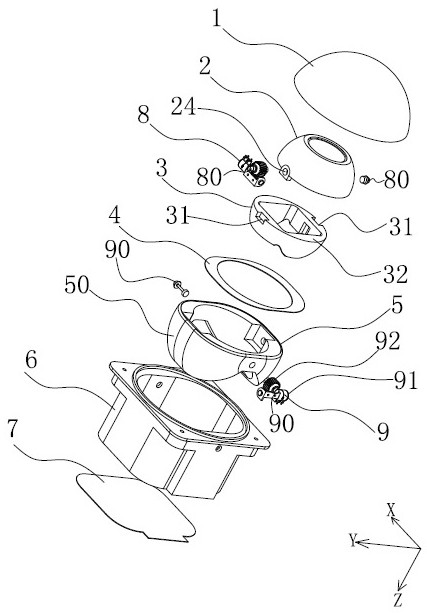
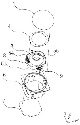
[0050] In this embodiment, the X-axis and the Y-axis are located on a horizontal plane, and they are vertically connected, while the Z-axis is perpendicular to the intersection of the X-axis and the Y-axis, and the Z-axis can be understood as an optical axis.
[0051] Such as figure 1 and figure 2 As shown, an optical drive device of the present invention includes a top cover 1, a fixed outer frame 6 and a bottom cover 7, and the fixed outer frame 6 is provided with an inner ball bracket A and an anti-shake middle frame 5 sequentially from inside to outside.
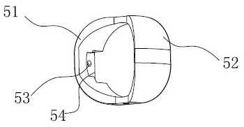
[0052] Such as image 3 and Figure 4 As shown, the anti-shake middle frame 5 includes a first ear cover 51 and a second ear cover 52 , and the first ear cover 51 and the second ear cover 52 are respectively distributed on both sides of the X axis. The first ear cover plate 51 and the second ear cover plate 52 are connected together to form an integrated structure, and the outer wall of the first ear cover plate 51 i...
Embodiment 2
[0068] Such as Figure 10 As shown, this embodiment provides a lens driving device, which has the optical driving device described in Embodiment 1, and
[0069] The lens carrier is fixed in the inner ball bracket A of the optical driving device. The lens carrier can be an AF motor or a single carrier.
[0070] Further, the lens driving device further includes a sensor assembly fixed on the lower end of the lens carrier, and the sensor assembly is connected to the bent flexible power supply board. The sensor component may be a Hall sensor, which is used to detect the position of the lens carrier after movement, ie, the position on the optical axis.
Embodiment 3
[0072] Based on Example 2, such as Figure 11 As shown, this embodiment provides an imaging device, which has the lens driving device described in the second embodiment. For example, mods with lenses, etc.
PUM
 Abstract
Description
Claims
Application Information
 - R&D Engineer
- R&D Manager
- IP Professional
- Industry Leading Data Capabilities
- Powerful AI technology
- Patent DNA Extraction
Browse by: Latest US Patents, China's latest patents, Technical Efficacy Thesaurus, Application Domain, Technology Topic, Popular Technical Reports.
© 2024 PatSnap. All rights reserved.Legal|Privacy policy|Modern Slavery Act Transparency Statement|Sitemap|About US| Contact US: help@patsnap.com