
An electric field generator with adjustable electric field generating position and its adjustment method

An electric field generator and electric field technology are applied in the field of electric field generators with adjustable electric field generation positions and their adjustment fields, which can solve the problems of inconvenient handling and installation, inconvenient handling and installation, inconvenient movement, installation and disassembly, etc. Reduce the difficulty of installation and movement, facilitate movement and installation, and facilitate the effect of assembly and movement

Active Publication Date: 2021-11-02
南京洛仑电磁科技有限公司
View PDF0 Cites 0 Cited by
  • Summary
  • Abstract
  • Description
  • Claims
  • Application Information

AI Technical Summary

Problems solved by technology

[0004] The above-mentioned existing technical solutions have the following defects: the electrification pole body of the electric field generator generally uses a solid metal pole body as the electrification conductor, but the weight of the solid electrification pole body is abnormally large, which leads to inconvenience in overall handling and installation, and the larger volume of the electric field The energized rod body required by the generator is even more huge, which makes it inconvenient to move, install and disassemble as a whole, which inconveniently requires a lot of manpower for handling and installation, and is inconvenient to construct the electric field as a whole, thus reducing the overall flexibility

Method used


Image

  • An electric field generator with adjustable electric field generating position and its adjustment method
  • An electric field generator with adjustable electric field generating position and its adjustment method
  • An electric field generator with adjustable electric field generating position and its adjustment method

Examples


Embodiment 1

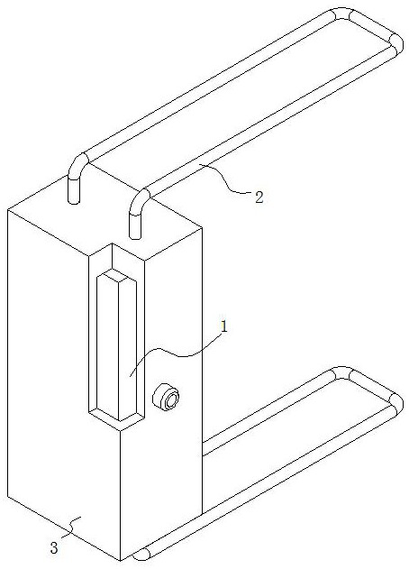
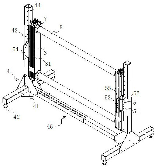
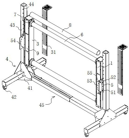
[0034] refer to figure 2 and image 3 , an electric field generator with adjustable electric field generating position, comprising a power supply mechanism 1 and a mounting bracket 4, the side wall of the mounting bracket 4 is detachably connected with a positioning frame body 5 for fixing the power supply mechanism 1, and the two ends of the power supply mechanism 1 are electrically connected There is a energized sheet 6, and the outer mounting shell 3 of the power supply mechanism 1 is provided with a positioning installation groove 7 for the energized sheet 6 to pass through. The inside of the positioning installation groove 7 is detachably connected with a plastic sleeve 8 for the energized sheet 6 to be shaped. The tube 8 is located on the outer wall of the energized sheet 6, and the end of the energized sheet 6 away from the power supply mechanism 1 is electrically connected to a conductive electrode 9. The energized sheet 6 is shaped and installed through an inflatable...

Embodiment 2

[0036] refer to Figure 6, an electric field generator with adjustable electric field generating position, comprising a power supply mechanism 1 and a mounting bracket 4, the side wall of the mounting bracket 4 is detachably connected with a positioning frame body 5 for fixing the power supply mechanism 1, and the two ends of the power supply mechanism 1 are electrically connected There is a energized sheet 6, and the outer mounting shell 3 of the power supply mechanism 1 is provided with a positioning installation groove 7 for the energized sheet 6 to pass through. The inside of the positioning installation groove 7 is detachably connected with a plastic sleeve 8 for the energized sheet 6 to be shaped. The barrel 8 is located on the inner wall of the energized sheet 6, and the end of the energized sheet 6 away from the power supply mechanism 1 is electrically connected to a conductive electrode 9. The plastic sleeve 8 is used to shape the inner wall of the energized sheet 6, a...

Embodiment 3

[0038] refer to Figure 7 , an electric field generator with adjustable electric field generating position, comprising a power supply mechanism 1 and a mounting bracket 4, the side wall of the mounting bracket 4 is detachably connected with a positioning frame body 5 for fixing the power supply mechanism 1, and the two ends of the power supply mechanism 1 are electrically connected There is a energized sheet 6, and the outer mounting shell 3 of the power supply mechanism 1 is provided with a positioning installation groove 7 for the energized sheet 6 to pass through. The inside of the positioning installation groove 7 is detachably connected with a plastic sleeve 8 for the energized sheet 6 to be shaped. The tube 8 is located on the inner wall of the energized sheet 6, and the outer wall of the energized sheet 6 has through holes. The end of the energized sheet 6 away from the power supply mechanism 1 is electrically connected to the conductive electrode 9, and the through hole...


PUM


Abstract

The invention discloses an electric field generator with an adjustable electric field generating position and an adjustment method thereof, which relates to the technical field of electric field generators, and aims to solve the problem that the weight of the electrified rod body of the electric field generator is abnormally large, which causes inconvenience in overall transportation and installation, and The problem of overall flexibility is reduced, and the key point of the technical solution is to include a power supply mechanism and a mounting bracket, the side wall of the mounting bracket is detachably connected with a positioning frame body for fixing the power supply mechanism, and the two ends of the power supply mechanism are electrically connected to energized sheets , the outer mounting shell of the power supply mechanism is provided with a positioning installation slot for passing the energized sheet, and a plastic sleeve for shaping the energized sheet is detachably connected to the inside of the positioning installation slot, and the energized sheet is far away from one end of the power supply mechanism The conductive electrodes are electrically connected. The effects of convenient assembly and movement, adjustable electric field generation and convenient disassembly are achieved.

Description

technical field [0001] The invention relates to the technical field of electric field generators, in particular to an electric field generator with an adjustable electric field generating position and an adjustment method thereof. Background technique [0002] With the rapid development of advanced science and technology, the increasing number of electronic equipment and rapid replacement, the electromagnetic environment caused by it is also in a complex and changeable state. Therefore, electromagnetic compatibility issues have attracted attention from various fields. In order to ensure that various electronic systems And devices can work normally in the harsh electromagnetic environment that may be encountered. It is necessary to conduct electromagnetic compatibility tests on them in advance, that is, to test whether they can withstand the interference of a certain intensity of external electromagnetic fields, or whether they generate electromagnetic radiation interference t...

Claims


Application Information

Patent Timeline
Patent Type & Authority Patents(China)
IPC IPC(8): G01R1/28G01R1/04G01R1/02
CPCG01R1/28G01R1/0408G01R1/02
Inventor 吴钟杰朱宇峰赵李刚
Owner 南京洛仑电磁科技有限公司
Learn More