
Hydraulic drive robot joint stepless speed change device

A technology of continuously variable speed change device and robot joint, which is applied in transmission device, gear transmission device, fluid transmission device, etc., can solve the problems of difficult to exert the optimal performance of the motor, unapplied, complex structure, etc.

Pending Publication Date: 2021-09-10
HEFEI INSTITUTES OF PHYSICAL SCIENCE - CHINESE ACAD OF SCI
View PDF0 Cites 0 Cited by
  • Summary
  • Abstract
  • Description
  • Claims
  • Application Information

AI Technical Summary

Problems solved by technology

Due to the particularity of the work, the output speed and torque of the robot joint need to be changed frequently. When the robot joint uses a motor with a fixed speed ratio reducer to work, the fixed speed ratio will cause the joint to work far below the peak efficiency or peak power of the motor. , this matching method is difficult to give full play to the optimal performance of the motor
Variable ratio reducers enable motors to operate near their peak efficiency or peak power, but have not been used in robotics products due to their size, weight, and complex structure

Method used


Image

  • Hydraulic drive robot joint stepless speed change device
  • Hydraulic drive robot joint stepless speed change device
  • Hydraulic drive robot joint stepless speed change device

Examples


Embodiment Construction

[0028] In order to make the purpose, technical solutions and advantages of the embodiments of the present invention clearer, the technical solutions in the embodiments of the present invention will be clearly and completely described below in conjunction with the embodiments of the present invention. Obviously, the described embodiments are part of the present invention Examples, not all examples. Based on the embodiments of the present invention, all other embodiments obtained by persons of ordinary skill in the art without creative efforts fall within the protection scope of the present invention.

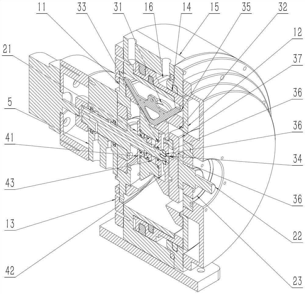
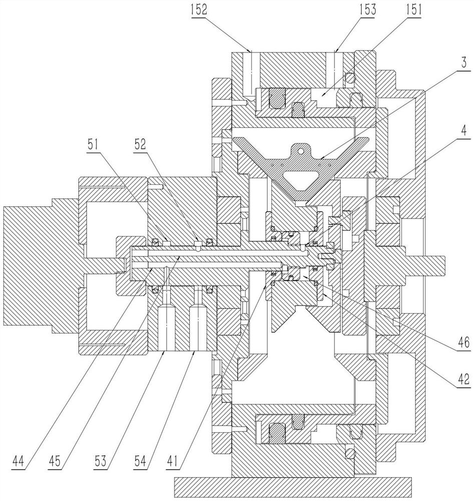
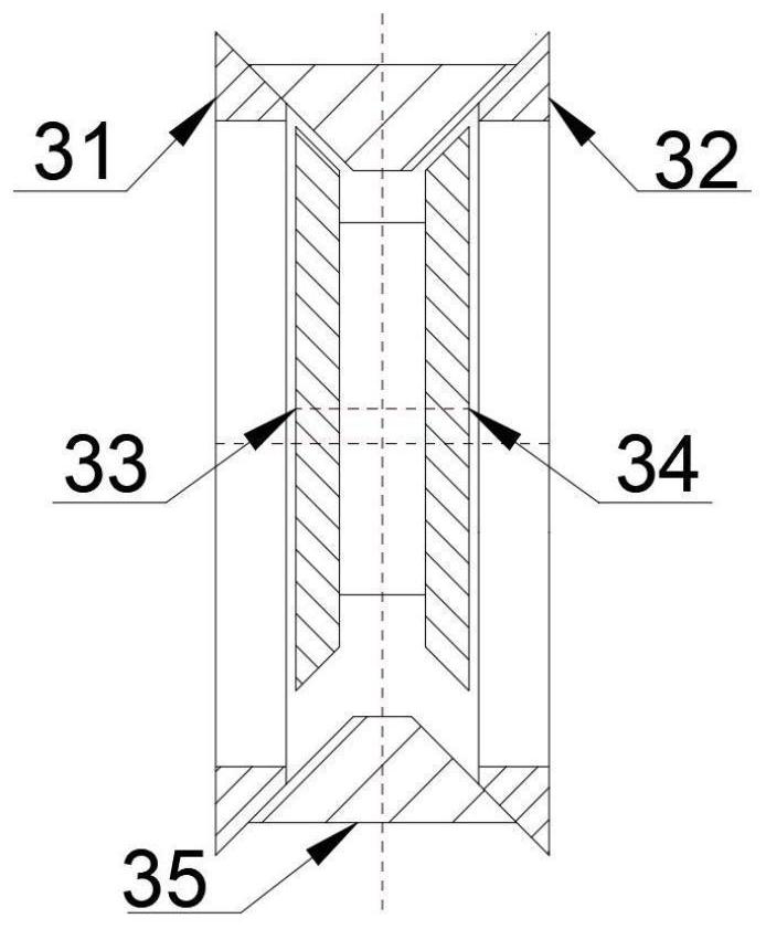
[0029] Such as Figure 1 ~ Figure 2As shown, its structural relationship is: the left end cover 13 and the right end cover 14 are respectively connected and fixed to the left and right ends of the annular cylinder 15, forming a cavity with the annular cylinder 15, and the left bracket 11 and the right bracket 12 are respectively arranged in the cavity The left and right sides of...


PUM


Abstract

The invention discloses a hydraulic drive robot joint stepless speed change device, and relates to the technical field of speed change devices. A left end cover and a right end cover connected to two ends of an annular cylinder barrel are used as supporting structures; an eccentric input shaft and an eccentric output shaft serving as an input end and an output end are rotationally mounted respectively; and the power of the input end is transmitted to the output end after being autonomously regulated and changed by a belt drive speed change mechanism. According to the hydraulic drive robot joint stepless speed change device provided by the invention, a right sun belt wheel on a right support and a left planet belt wheel on the eccentric output shaft can move in the axial direction under hydraulic driving, so that the axial distance between a left sun belt wheel and the right sun belt wheel and the axial distance between a left planet belt wheel and a right planet belt wheel are adjusted, so that the effective working radius of the pair of sun belt wheels and the effective working radius of the pair of planet wheels are changed, and the adjustment of the transmission ratio, namely stepless speed change, is realized; the output shaft is axially limited and rotatably mounted on the right end cover, so that the axial floating of the output shaft is effectively avoided, and the power output by the stepless speed change device is more stable.

Description

technical field [0001] The invention relates to the technical field of speed change devices, in particular to a continuously variable speed change device for robot joints. Background technique [0002] The robot system is a whole composed of the robot, the operating object and the environment, including four parts: the mechanical system, the drive system, the control system and the perception system. A robot is an automated machine that has some intelligent abilities similar to humans or creatures, such as perception, planning, action, and coordination. It is an automated machine with high flexibility. The robot body mainly includes three key components: reducer, controller, and drive motor. They also occupy a large part of the cost of the robot industry, and together determine the performance, quality and price of the product. [0003] As a key component of the robot system, the reducer has an important impact on the overall performance of the robot system. At the same ti...

Claims


Application Information

Patent Timeline
Patent Type & Authority Applications(China)
IPC IPC(8): F16H1/32F16H47/04
CPCF16H1/32F16H47/04
Inventor 徐林森刘志鹏刘进福叶晓东龙杰刘磊吕志朋梁兴灿周爽韩松
Owner HEFEI INSTITUTES OF PHYSICAL SCIENCE - CHINESE ACAD OF SCI
Learn More