
Engine-driven generator and control method and system thereof

A technology of engine drive and control method, which is applied in the direction of engine control, engine ignition, engine components, etc., and can solve the problems of threatening the life safety of personnel, narrow displacement range, and the cost of signal acquisition and response.

Active Publication Date: 2021-09-10
LONCIN MOTOR +2
View PDF17 Cites 0 Cited by
  • Summary
  • Abstract
  • Description
  • Claims
  • Application Information

AI Technical Summary

Problems solved by technology

However, in the actual test, there is a period of time between the two adjacent data collections of the CO alarm, and it will take a while for the data to be fed back to the control system for data processing, that is, it will take a while for the signal to be collected and responded
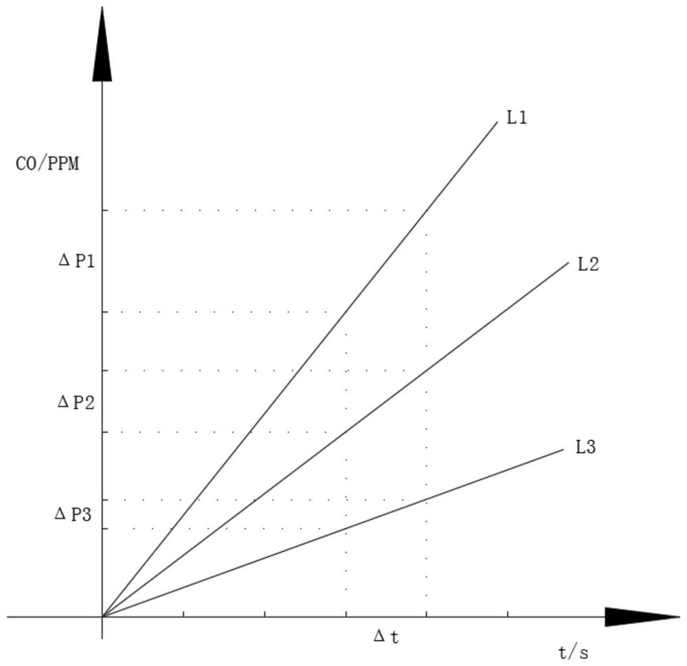
[0005] At the same time, in the process of practice, the inventor found that: in the engine-driven generators of the prior art, the CO alarms are specially designed for engines with a certain displacement, and the applicable displacement range is relatively narrow, so they cannot be used For engines with a larger or smaller displacement range, the reason for this is: in a certain space, under ideal conditions, the rate of CO produced by the engine increases linearly, please refer to figure 1 , L1, L2, and L3 respectively represent the rate lines of CO production by engines with large displacement, medium displacement, and small displacement, which are given by figure 1 It can be seen that ΔP1>ΔP2>ΔP3, that is, the larger the displacement of the engine, the larger the increase Δp of CO concentration within the same interval time Δt
[0006] Therefore, an engine with a larger displacement tends to produce more CO at a faster rate in a certain space, but it takes a while for the signal to be collected and responded, and the engine will continue to produce a large amount of CO during this period, resulting in When the specially designed CO alarm is alarming, the CO concentration in the environment has exceeded the preset safety threshold and threatens the life safety of people in the environment, and the alarm does not respond in time and delays the alarm.

Method used


Image

  • Engine-driven generator and control method and system thereof
  • Engine-driven generator and control method and system thereof
  • Engine-driven generator and control method and system thereof

Examples


Embodiment Construction

[0043] The following will clearly and completely describe the technical solutions in the embodiments of the present invention with reference to the accompanying drawings in the embodiments of the present invention. Obviously, the described embodiments are only some, not all, embodiments of the present invention. Based on the embodiments of the present invention, all other embodiments obtained by persons of ordinary skill in the art without making creative efforts belong to the protection scope of the present invention.

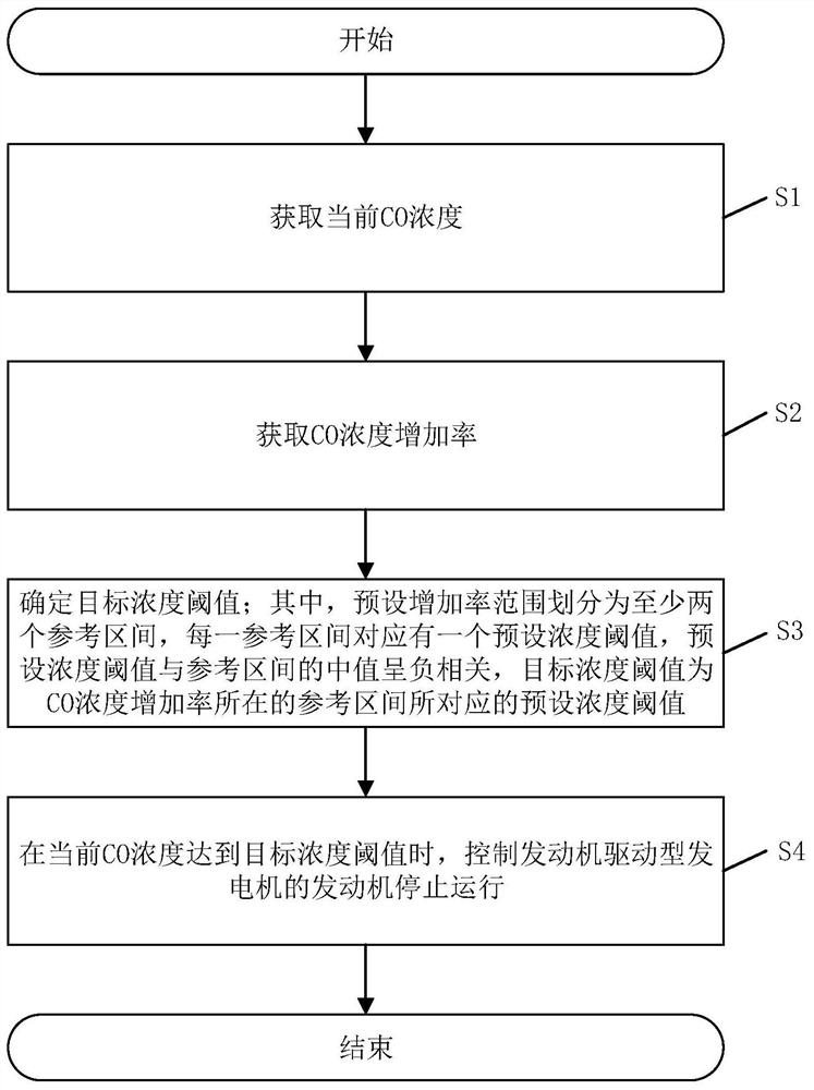
[0044] Please refer to figure 2 , the control method of the engine-driven generator provided by the present application includes the following steps:

[0045] Step S1, obtaining the current CO concentration.

[0046] Specifically, the current CO concentration refers to the CO concentration measured in a certain space during the working process of the engine-driven generator, and the current CO concentration is an actual measured value, which can be detected ...


PUM


Abstract

The invention discloses an engine-driven generator and a control method and system thereof. The control method comprises the following steps that the current CO concentration is obtained, the CO concentration increasing rate is obtained, a target concentration threshold value is determined, and an engine of the engine-driven generator is controlled to stop running when the current CO concentration reaches the target concentration threshold value; wherein the preset increase rate range is divided into at least two reference intervals, each reference interval corresponds to a preset concentration threshold value, the preset concentration threshold value is in negative correlation with a median value of the reference intervals, and the target concentration threshold value is the preset concentration threshold value corresponding to the reference interval where the CO concentration increasing rate is located. According to the control method, the appropriate target concentration threshold value can be determined according to the CO concentration increasing rate, so that the engine is controlled to stop in advance or in a delayed manner, the purpose of preventing the CO concentration from exceeding the standard is achieved, and the safety of a user is improved.

Description

technical field [0001] The present invention relates to the technical field of generators, and more specifically relates to an engine-driven generator and its control method and control system. Background technique [0002] Small emergency generators are usually suitable for households, small businesses, etc., and their power is mostly internal combustion engines such as general-purpose engines with relatively small displacement, and gasoline is mostly used as fuel. This kind of engine-driven generator is usually placed in relatively small and relatively closed spaces such as basements and utility rooms when in use. Since the exhaust gas generated during its work contains carbon monoxide (CO), CO will be released in a limited space. When the CO concentration reaches a certain limit, it may bring the danger of CO poisoning to the personnel in the space. [0003] In order to prevent such hazards, the existing technology will be equipped with a CO alarm, which collects the con...

Claims


Application Information

Patent Timeline
IPC IPC(8): F02D29/06F02B63/04F02B77/08F02P9/00
CPCF02B63/04F02D29/06F02B77/08F02P9/00Y02T10/40
Inventor 田辉李杨杜锡虎张明鸿
Owner LONCIN MOTOR
Learn More