Multifunctional advanced protective barrier, protective fence and monitoring method

A protective railing, multi-functional technology, applied in the field of protective fence and monitoring, multi-functional advanced protective railing, can solve the problems of major safety hazards, inability to set up, inability to monitor status, etc.

Pending Publication Date: 2021-09-10
SHANGHAI NO 4 CONSTR
View PDF7 Cites 0 Cited by
  • Summary
  • Abstract
  • Description
  • Claims
  • Application Information

AI Technical Summary

Problems solved by technology

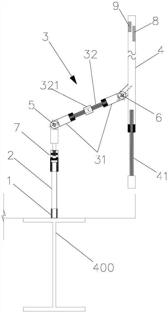
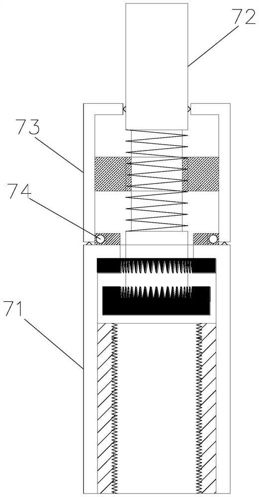
[0003] The present invention solves the problem that the existing protective fence cannot be installed before the laminated slabs are poured into shape, and the secondary erection and dismantling are labor-intensive and material-intensive, and there are major safety hazards, and at the same time, the state cannot be monitored. The technical solution adopted is: one A multifunctional advanced protective railing, comprising: a base, a connecting rod, an oblique arm and a vertical bar, the base, the connecting rod, the oblique arm, and the vertical rod are connected in sequence, and the connecting rod and the oblique arm are connected by a first joint connection, the oblique arm and the vertical rod are connected through a second joint;

Method used


Image

  • Multifunctional advanced protective barrier, protective fence and monitoring method
  • Multifunctional advanced protective barrier, protective fence and monitoring method
  • Multifunctional advanced protective barrier, protective fence and monitoring method

Examples


Embodiment Construction

[0030] The present invention is described in further detail now in conjunction with accompanying drawing. These drawings are all simplified schematic diagrams, which only illustrate the basic structure of the present invention in a schematic manner, so they only show the configurations related to the present invention.

[0031] In describing the invention, it is to be understood that the terms "center", "longitudinal", "transverse", "length", "width", "thickness", "upper", "lower", "front", "rear ", "Left", "Right", "Vertical", "Horizontal", "Top", "Bottom", "Inner", "Outer", "Clockwise", "Counterclockwise", etc. Based on the orientation or positional relationship shown in the drawings, it is only for the convenience of describing the invention and simplifying the description, rather than indicating or implying that the referred device or element must have a specific orientation, be constructed and operated in a specific orientation, and therefore cannot be understood for lim...


PUM


Abstract

The invention discloses a multifunctional advanced protective barrier, a protective fence and a monitoring method. The multifunctional advanced protective barrier comprises a base, a connecting rod, an inclined arm and a vertical rod, the connecting rod is connected with the inclined arm through a first joint, and the inclined arm is connected with the vertical rod through a second joint; at least one end of the vertical rod is provided with a second telescopic rod, the vertical rod is internally provided with a resistance metering device and a signal transmitting device with an ID identity code, and the signal transmitting device is connected with a computer. According to the multifunctional advanced protective barrier, the protective fence and the monitoring method, due to the fact that the inclined arm is arranged, the protective range of the protective barrier is expanded to the position outside the fixed position of the bottom of the protective barrier, and comprehensive safety protection is conducted on the free face of a composite floor slab to be constructed in advance. And meanwhile, an inclination angle of the inclined arm and the vertical rod can be adjusted through the first joint and the second joint, and therefore the protection range can be adjusted according to needs. Moreover, the installation state of the protective fence can be monitored in real time by measuring the resistance of the vertical rod.

Description

technical field [0001] The invention relates to the technical field of building construction, in particular to a multifunctional advanced protective railing, a protective fence and a monitoring method. Background technique [0002] During the construction of the steel structure (prefabricated structure) on the construction site, there are many cases where there are superimposed cantilevered floor slabs (such as profiled steel plates, row frame ribs, etc.) outside the structural beams. Before the laminated slab is poured and formed, it is generally impossible to set conventional safety guardrails on the laminated slab alone. Usually, before the composite slab is poured and formed, the railings are set on the steel beam (prefabricated composite beam), and the external cantilevered composite slab area is in a blind area without safety protection. After the pouring of the laminated slab is completed, the protective railing is turned over to the edge of the laminated slab, and t...

Claims


Application Information

Patent Timeline
IPC IPC(8): E04G21/32G01D21/00
CPCE04G21/3204E04G21/3223G01D21/00
Inventor 马晓辉杜梦玮殷凯俞水情俞文俊张文成尹晓洁
Owner SHANGHAI NO 4 CONSTR
Why Eureka
Try Eureka