Cylindrical cone type relay pump valve device of automobile and braking method and application of cylindrical cone type relay pump valve device

A relay valve, cylinder technology, applied in the field of automobile braking, can solve the problem of heavy stepping on the brake and other problems

Pending Publication Date: 2021-09-10
沈阳义嘉仁卡客汽车技术有限公司
View PDF0 Cites 0 Cited by
  • Summary
  • Abstract
  • Description
  • Claims
  • Application Information

AI Technical Summary

Problems solved by technology

[0004] Aiming at the problems in the prior art of the air pressure braking technology device that the emergency brake is lightly stepped and the brake is not effective when the heavy step is applied, the present invention provides a cylindrical cone type relay pump valve device for automobiles and its braking method and application. The high-pressure gas pushes the cylindrical cone and then pushes the brake moving groove and the brake roller to achieve the purpose of valve opening, so that the high-pressure gas enters the inner cavity of the relay valve, and the high-pressure gas generated by the relay valve is delivered to each brake through the brake air channel. Slave cylinder to achieve good braking effect

Method used


Image

  • Cylindrical cone type relay pump valve device of automobile and braking method and application of cylindrical cone type relay pump valve device
  • Cylindrical cone type relay pump valve device of automobile and braking method and application of cylindrical cone type relay pump valve device
  • Cylindrical cone type relay pump valve device of automobile and braking method and application of cylindrical cone type relay pump valve device

Examples


Embodiment 1

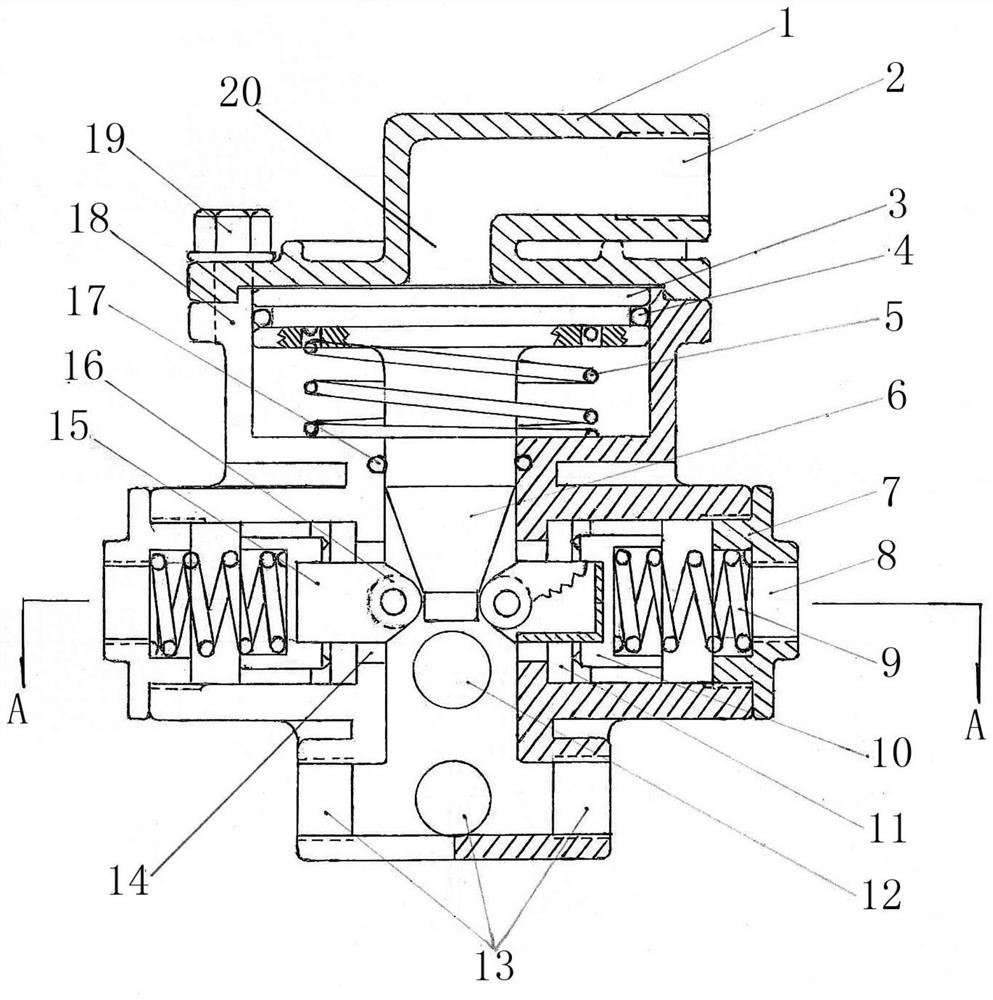
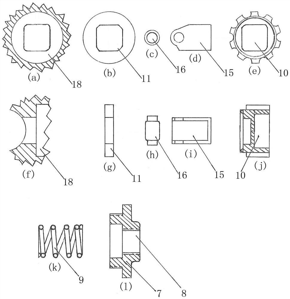
[0054] like Figure 1-4 As shown, a cylindrical cone type relay pump valve device for automobiles, the relay pump valve device includes a relay valve top cover 1, master cylinder inlet and outlet air passage I2, brake piston 3, brake piston sealing ring 4, brake piston Return spring 5, cylindrical cone 6, air intake screw cover 7, air intake 8, air intake pressure spring 9, air intake pressure valve body 10, air intake rubber gasket 11, exhaust air 12, Brake air channel 13, housing square hole square hole 14, brake moving groove 15, brake roller 16, brake sealing ring 17, relay valve housing 18, assembly bolt 19, brake chamber 20, exhaust Road rubber gasket 21, exhaust port opening and closing valve body 22, exhaust port sealing ring 23, exhaust port screw cover 24, master pump inlet and outlet air channel II 25 and exhaust hole 26;

[0055] The top of the relay valve housing 18 is equipped with a relay valve top cover 1, and the relay valve top cover 1 and the relay valve ho...

Embodiment 2

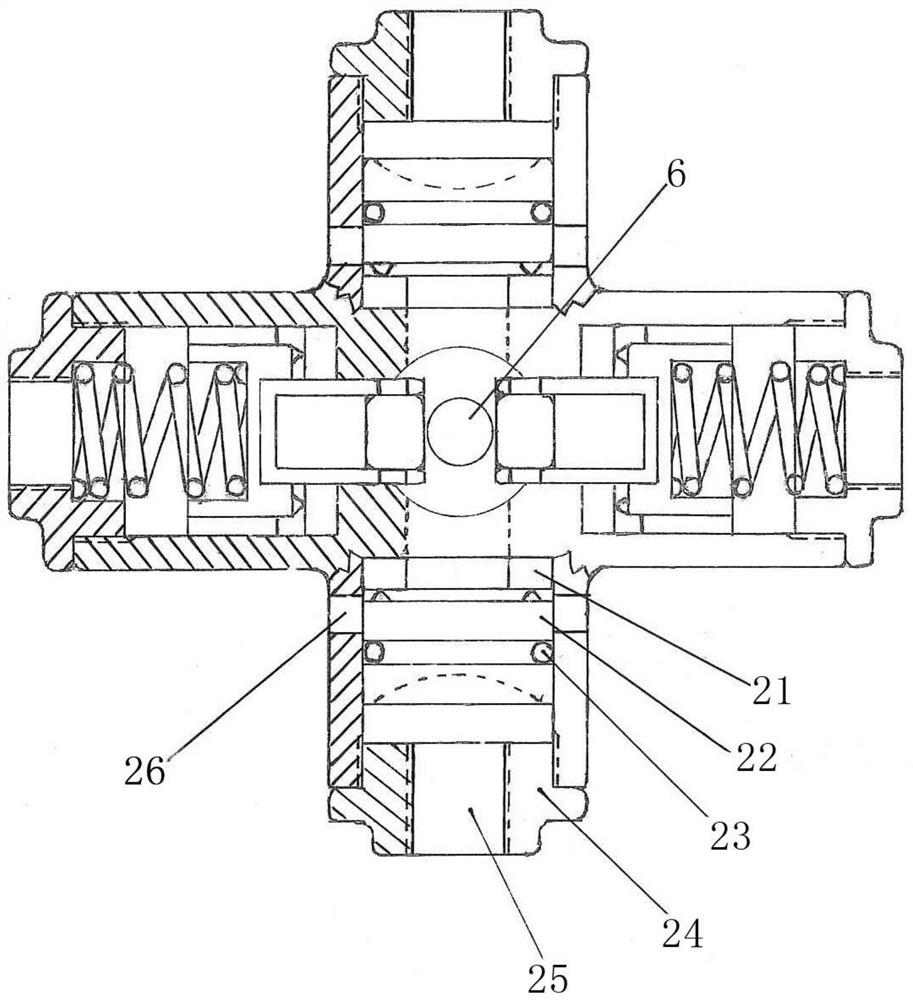
[0076] like Figure 5-6 As shown, a cylindrical cone type relay pump valve device for automobiles, the relay pump valve device includes a relay valve top cover 1, master cylinder inlet and outlet air passage I2, brake piston 3, brake piston sealing ring 4, brake piston Return spring 5, cylindrical cone 6, air intake screw cover 7, air intake 8, air intake pressure spring 9, air intake pressure valve body 10, air intake rubber gasket 11, exhaust air 12, Brake air channel 13, housing square hole 14, brake moving steel ball II 15, brake moving steel ball I 16, brake sealing ring 17, relay valve housing 18, assembly bolt 19, brake air chamber 20, exhaust Air duct rubber gasket 21, exhaust duct opening and closing valve body 22, exhaust duct sealing ring 23, exhaust duct screw cover 24, master pump inlet and outlet duct II 25 and exhaust hole 26;

[0077] The top of the relay valve housing 18 is equipped with a relay valve top cover 1, and the relay valve top cover 1 and the relay...


PUM


Abstract

The invention discloses an automobile cylindrical cone type relay pump valve device and a braking method and application thereof, and belongs to the technical field of automobile braking. The relay pump valve device comprises a relay valve top cover, a master pump air inlet and outlet channel I, a brake piston, a brake piston return spring, a cylindrical cone, an air inlet channel, an air inlet channel pressure spring, an air inlet channel pressure valve body, an air inlet channel rubber sealing gasket, an exhaust channel, a brake air channel, a shell square hole, a brake moving groove, a brake roller, a relay valve shell, a brake air chamber and the like. According to the device, the cylindrical cone is arranged below the brake piston, the brake piston drives the cylindrical cone to move downwards under the action of high-pressure air flow, a brake roller or a brake moving steel ball can be quickly and accurately pushed, a contact interface is gradually changed, braking is flexible, and the effects of light treading deceleration and heavy treading emergency braking can be effectively achieved; therefore, the problems that in the prior art, due to the fact that a relay valve is inflexible in braking, emergency braking is caused by light treading, and braking is inflexible due to heavy treading are effectively solved, and the rapid and accurate speed reduction or braking effect is achieved.

Description

technical field [0001] The invention belongs to the technical field of automobile braking, and in particular relates to a cylindrical-cone relay pump valve for an automobile braking system, and a braking method and application of the relay pump valve. Background technique [0002] When the car is running or parking, it needs a good braking system to slow down or stop in time to ensure the safety of the car. At present, there are two kinds of braking systems used in automobiles: one is hydraulic braking technology device, and the other is pneumatic braking technology device. Among them, the pneumatic brake technology device is mainly composed of an air pump, an air storage tank, a master cylinder, a relay valve and a sub-pump. Its main working process is as follows: the air pump (also called air compressor) is driven by the engine, compresses the air into high-pressure gas, and stores it in more than two air storage tanks. The pumps are connected; the other air storage tank...

Claims


Application Information

Patent Timeline
Patent Type & Authority Applications(China)
IPC IPC(8): B60T13/26B60T15/02B60T15/18
CPCB60T13/26B60T15/02B60T15/18
Inventor 戎华庆李晓光王裕喜
Owner 沈阳义嘉仁卡客汽车技术有限公司
Why Eureka
Try Eureka