Bending and locking device and method for small positioner in narrow space

A narrow space, locking device technology, applied in the direction of hand-held tools, manufacturing tools, etc., can solve the problem of small size of the positioner, difficult to fix, small operating space, etc.

Active Publication Date: 2021-09-10
AECC AVIATION POWER CO LTD
View PDF5 Cites 0 Cited by
  • Summary
  • Abstract
  • Description
  • Claims
  • Application Information

AI Technical Summary

Problems solved by technology

[0007] For the assembly of blades in a narrow space, due to the small operating space and blind spots during installation, and the small size of the positioner, it is difficult to fix. If the traditional knocking method is used for installation, multiple people are required to complete the installation, which takes a long time and is difficult to operate. And there is a risk of damaging the rotor

Method used


Image

  • Bending and locking device and method for small positioner in narrow space
  • Bending and locking device and method for small positioner in narrow space
  • Bending and locking device and method for small positioner in narrow space

Examples


Embodiment Construction

[0041] The present invention will be further described in detail below in conjunction with the accompanying drawings and specific embodiments, which are explanations of the present invention rather than limitations.

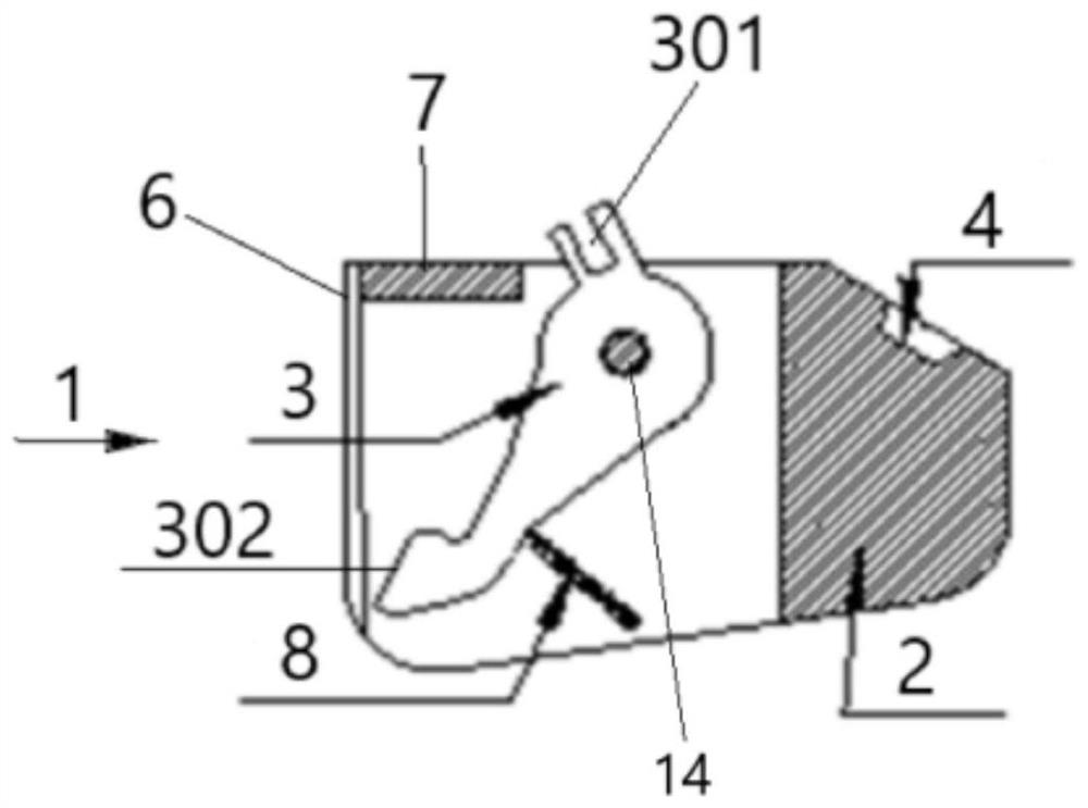
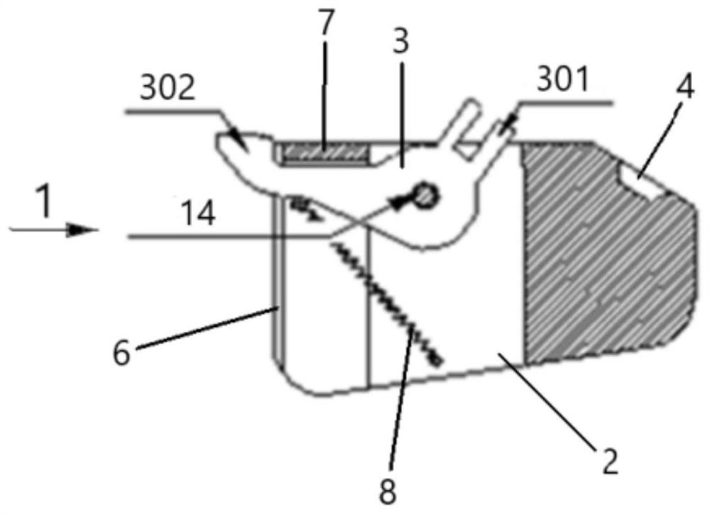
[0042] Such as figure 1 and 2 As shown, a small positioner bending locking device in a narrow space includes a guide block 2 and a locking bridge 3; the guide block 2 is provided with a guide groove 6 connecting the upper end and the front end; the locking bridge 3 Rotate along the slotting direction and be arranged in the guide groove 6. The driving end of the locking bridge 3 is provided with a locking bridge rotation slot 301, and its working end is provided with a locking plane 302 of the locking bridge; The locking plane 302 of the tight bridge is parallel to the upper end of the guide block 2 and not lower than the upper end of the guide block 2, and the locking bridge 3 is arranged as a crank arm.

[0043] In the present invention, the bending locking de...


PUM


Abstract

The invention provides a bending and locking device and method for a small positioner in a narrow space. The small positioner can be quickly and accurately locked and fixed in a limited space, and unnecessary mechanical damage is avoided while the assembly purpose is completed. The bending and locking device comprises a guide block and a locking bridge piece, and a guide groove communicating with the upper end and the front end is formed in the guide block; the locking bridge piece is rotatably arranged in the guide groove in the grooving direction, a locking bridge piece rotating inserting groove is formed in the driving end of the locking bridge piece, and a locking bridge piece locking plane is arranged at the working end of the locking bridge piece; and in the locking state, the locking bridge piece locking plane is parallel to the upper end of the guide block and is not lower than the upper end of the guide block.

Description

technical field [0001] The invention belongs to the field of assembly of aeroengine blades, and in particular relates to a bending locking device and method for a small positioner in a narrow space. Background technique [0002] Among the aeroengines, the number of blades is the largest, and the engine relies on numerous blades to complete the compression and expansion of the gas and generate powerful power with the highest efficiency to propel the aircraft forward. However, the blade is a special part, which has a large number, complex shape, high requirements, difficult processing, and is a part with frequent failures. Various types of blades need to be installed on the engine to actually work and be strong. [0003] At present, the blades are generally installed and locked in the following ways: [0004] 1) Use bendable sheet devices such as locking pieces and positioners to bend and lock; [0005] 2) The pin shaft is used to connect the wheel disc and the blade instal...

Claims


Application Information

Patent Timeline
Patent Type & Authority Applications(China)
IPC IPC(8): B25B27/00
CPCB25B27/00
Inventor 曹朋刘晓龙陈金平樊铁艳何朝霞张澜禹刘晓坤张智礼
Owner AECC AVIATION POWER CO LTD
Why Eureka
Try Eureka