
Self-adaptive clamping device for steel pipe welding

A clamping device and self-adaptive technology, which is applied in the direction of auxiliary devices, welding equipment, auxiliary welding equipment, etc., can solve the problems of large arc surface fit, inability to adjust the welding gap of pipes, and incompatibility with multiple sizes, etc.

Inactive Publication Date: 2021-09-10
符致民
View PDF0 Cites 2 Cited by
  • Summary
  • Abstract
  • Description
  • Claims
  • Application Information

AI Technical Summary

Problems solved by technology

[0003] As a device for cooperation in the welding process, the welding auxiliary device is currently widely used in various fields. However, due to the arc shape of the pipe, there are problems such as incompatibility with pipes of various sizes and the inability to adjust the welding gap. It is because the clamp used to clamp the pipe is larger than the diameter of the pipe before clamping, and the gap between the surface of the pipe cutter and the surface of the pipe cutter after the complete fit is relatively large, so that the fixed position of the pipe when it receives part of the external force Deviations are prone to occur, so an adaptive clamping device for steel pipe welding has been invented to solve the above problems

Method used


Image

  • Self-adaptive clamping device for steel pipe welding
  • Self-adaptive clamping device for steel pipe welding
  • Self-adaptive clamping device for steel pipe welding

Examples


Embodiment Construction

[0026] The following will clearly and completely describe the technical solutions in the embodiments of the present invention with reference to the accompanying drawings in the embodiments of the present invention. Obviously, the described embodiments are only some, not all, embodiments of the present invention.

[0027] Examples of the described embodiments are shown in the drawings, wherein like or similar reference numerals designate like or similar elements or elements having the same or similar functions throughout. The embodiments described below by referring to the figures are exemplary and are intended to explain the present invention and should not be construed as limiting the present invention.

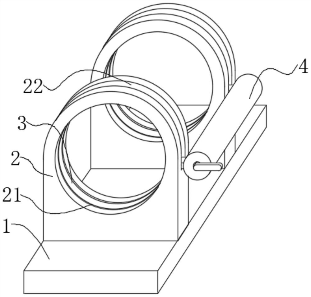
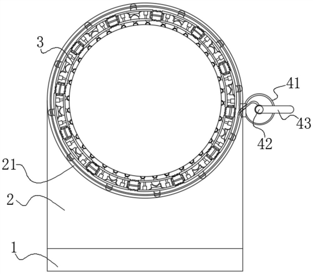
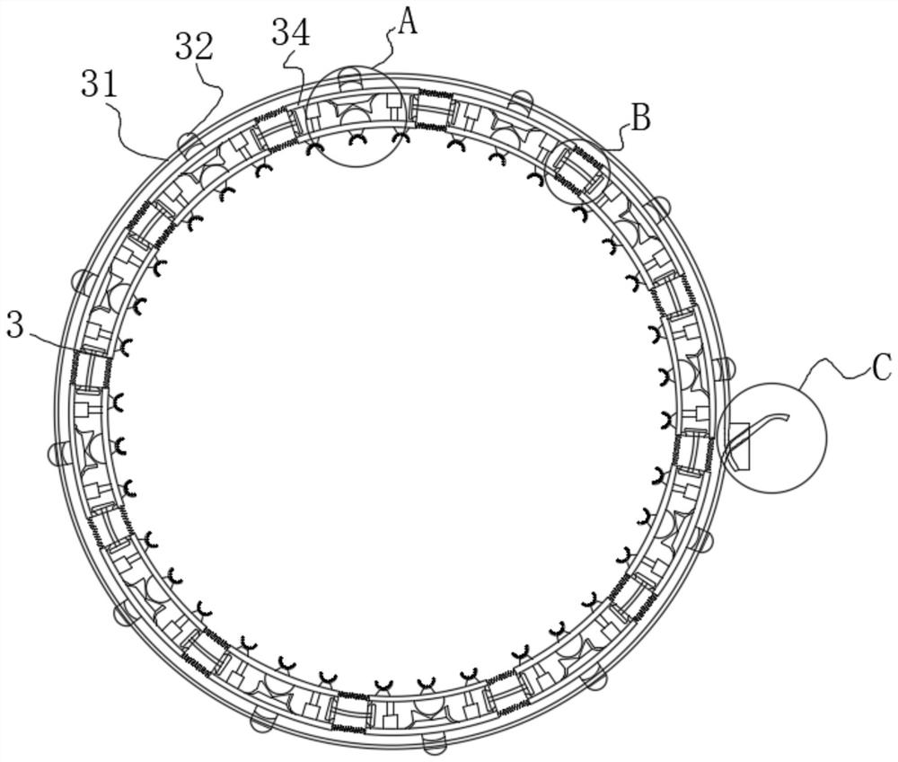
[0028] see Figure 1-8 , the present invention provides a technical solution: an adaptive clamping device for steel pipe welding, including a base 1, an accommodating ring frame 2, a clamping device 3 and a control device 4, and the base 1 is equipped with two accommodating ...


PUM


Abstract

The invention discloses a self-adaptive clamping device for steel pipe welding, and relates to the technical field of welding equipment. The self-adaptive clamping device for steel pipe welding comprises a base, accommodating ring frames, a clamping device body and a control device; the base is provided with the two accommodating ring frames; inner grooves are formed in the inner walls of the accommodating ring frames; the clamping device body is mounted in the inner grooves; the tops of the accommodating ring frames are in an arc shape; and outer semicircular grooves are formed in the tops of the accommodating ring frames. According to the self-adaptive clamping device for steel pipe welding, two steel pipes needing to be welded are inserted into the accommodating ring frames, an anti-clamping device is controlled by a control device to clamp the steel pipes in the accommodating ring frames so as to finish maximum-area fitting to the arc-surface steel pipes during clamping; and in addition, the two steel pipes can be rotated in the original positions by shifting the control device to move along the outer semicircular grooves, so that the problem that the working surfaces which are not welded are gradually welded under the condition that a clamp is not loosened is solved to reduce the tedious steps of people in the welding process.

Description

technical field [0001] The invention relates to the technical field of welding equipment, in particular to an adaptive clamping device for steel pipe welding. Background technique [0002] Welding, also known as welding, is a manufacturing process and technique that uses heat, high temperature, or pressure to join metal or other thermoplastic materials such as plastics. [0003] As a device for cooperation in the welding process, the welding auxiliary device is currently widely used in various fields. However, due to the arc shape of the pipe, there are problems such as incompatibility with pipes of various sizes and the inability to adjust the welding gap. It is because the clamp used to clamp the pipe is larger than the diameter of the pipe before clamping, and the gap between the surface of the pipe cutter and the surface of the pipe cutter after the complete fit is relatively large, so that the fixed position of the pipe when it receives part of the external force Devia...

Claims


Application Information

Patent Timeline
Patent Type & Authority Applications(China)
IPC IPC(8): B23K37/053B23K101/06
CPCB23K37/0533B23K2101/06
Inventor 符致民
Owner 符致民
Learn More