Discharging device of laser cutting machine

A technology of laser cutting machine and unloading device, which is applied in laser welding equipment, metal processing equipment, welding equipment, etc., and can solve the time-consuming and labor-intensive problems of plate unloading

Active Publication Date: 2021-09-10
ZHEJIANG BAOYE BUILDING MATERIAL TECH
View PDF7 Cites 1 Cited by
  • Summary
  • Abstract
  • Description
  • Claims
  • Application Information

AI Technical Summary

Problems solved by technology

[0003] Now the plate is usually placed on the platform of the laser cutting machine for processing the plate on the platform, but the unloading of the plate after processing is time-consuming and laborious

Method used


Image

  • Discharging device of laser cutting machine
  • Discharging device of laser cutting machine
  • Discharging device of laser cutting machine

Examples


Embodiment Construction

[0039] The following will clearly and completely describe the technical solutions in the embodiments of the present invention with reference to the accompanying drawings in the embodiments of the present invention. Obviously, the described embodiments are only some, not all, embodiments of the present invention. Based on the embodiments of the present invention, all other embodiments obtained by persons of ordinary skill in the art without making creative efforts belong to the protection scope of the present invention.

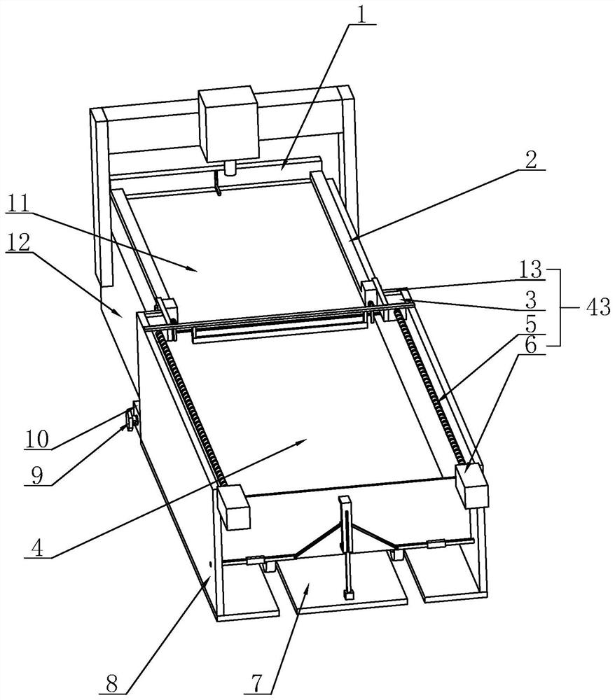
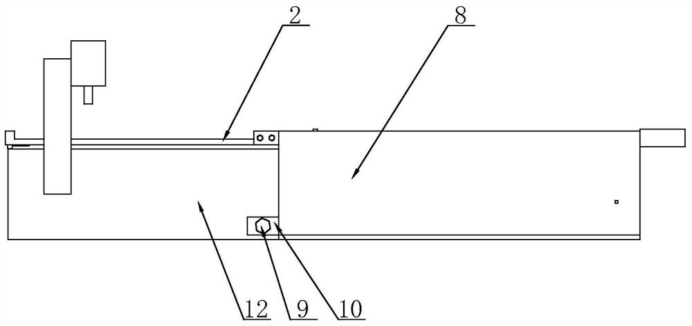
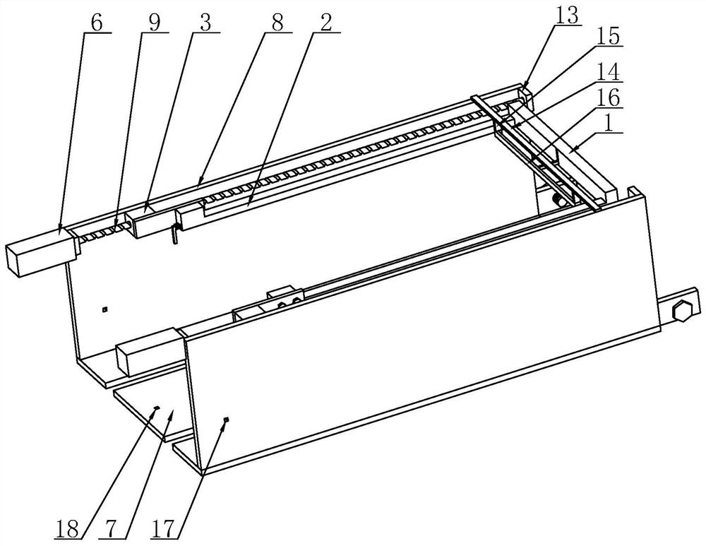
[0040] see Figure 1-Figure 12 , the present invention provides a technical solution for a laser cutting machine unloading device: a laser cutting machine unloading device,

[0041] Including a base plate 7, on which two parallel side plates 8 are fixed;

[0042] Two first telescopic devices 43 are respectively fixed on the opposite sides of the two side plates 8;

[0043] The two parallel rods 2 are respectively fixed on the two first telescopic devices 43 ...


PUM


Abstract

The invention discloses a discharging device of a laser cutting machine. The discharging device comprises a bottom plate, two first telescopic devices, two parallel rods, a connecting cross rod and a telescopic rod. Two side plates arranged in parallel are fixed to the bottom plate. The two first telescopic devices are fixed to the opposite side faces of the two side plates correspondingly. The two parallel rods are fixed to the two first telescopic devices correspondingly. The connecting cross rod is fixed between the two parallel rods. The connecting cross rod is provided with a telescopic groove with a downward opening, and the telescopic rod is installed in the telescopic groove and can move up and down relative to the telescopic groove. According to the discharging device of the laser cutting machine, after machining is completed, the first telescopic devices drive the connecting cross rod through the parallel rods to move above a plate, the telescopic rod is partly moved out of the telescopic groove, then the first telescopic rod drives the connecting cross rod to be folded, the telescopic rod drives the plate on a platform to move towards the side of the bottom plate in the folding process, and therefore the plate is pushed out of the platform, and discharging is completed.

Description

technical field [0001] The invention belongs to the technical field of laser cutting machines, and in particular relates to an unloading device of a laser cutting machine. Background technique [0002] The laser cutting machine focuses the laser emitted from the laser into a high-power-density laser beam through the optical path system. The laser beam irradiates the surface of the workpiece to make the workpiece reach the melting point or boiling point. At the same time, the high-pressure gas coaxial with the beam will melt or Vaporized metal is blown away, and laser cutting process uses invisible beam instead of traditional mechanical knife, which has the characteristics of high precision, fast cutting, not limited to cutting pattern, automatic typesetting saves material, smooth incision, low processing cost, etc. It will gradually improve or replace traditional metal cutting process equipment. [0003] Now the plate is usually placed on the platform of the laser cutting m...

Claims


Application Information

Patent Timeline
Patent Type & Authority Applications(China)
IPC IPC(8): B23K26/38B23K26/70
CPCB23K26/38B23K26/70B23K26/702
Inventor 王立峰李晶王盛炉鲍琴华唐春丰王亚雄李智文
Owner ZHEJIANG BAOYE BUILDING MATERIAL TECH
Why Eureka
Try Eureka