
Soldering equipment for printed circuit boards for the manufacture of electrical components

A technology for printed circuit boards and electrical components, which is applied in the direction of assembling printed circuits, welding equipment, and printed circuits with electrical components. Achieve the effect of improving welding quality, not easy to weld, and easy to operate

Active Publication Date: 2021-10-26
HAIMEN PURPLE PRINTING MACHINERY
View PDF0 Cites 0 Cited by
  • Summary
  • Abstract
  • Description
  • Claims
  • Application Information

AI Technical Summary

Problems solved by technology

[0004] Method 1 is relatively cumbersome to operate. Although the operation of Method 2 is relatively simple, the molten solder is given directly. If the operation is slightly improper, such as too much or too little material, it is easy to cause virtual welding or the surface of the solder joint is easy to protrude outward. phenomenon, and the solder is used too much, if it spreads out of the pad, it will cause accumulation near the solder joint, which will cause bridging. Bridging is a serious welding defect. It causes two solder joints that should not have electrical contact to have Electric contact, resulting in unsatisfactory welding effect

Method used


Image

  • Soldering equipment for printed circuit boards for the manufacture of electrical components
  • Soldering equipment for printed circuit boards for the manufacture of electrical components
  • Soldering equipment for printed circuit boards for the manufacture of electrical components

Examples


Embodiment 1

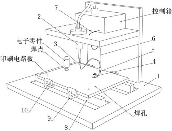
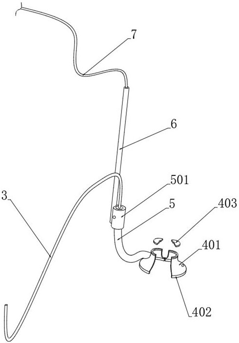
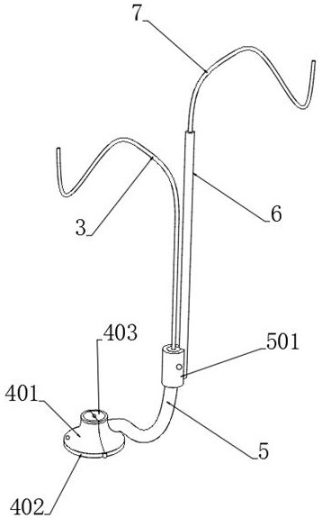
[0045] see Figure 1-3 , a welding equipment for printed circuit boards used in the manufacture of electrical components, comprising a control console 1 and a control box installed on the top of the console 1, and a feeding gun 2 connected to the control box is also installed on the top of the console 1, for The discharge end of the material gun 2 is connected to the mold plate 4 through the nozzle 3, the mold plate 4 is composed of a pair of horn-shaped mold petals 401 that are connected by rotation, and a pair of heat-insulating flexible pads 402 are provided with a connecting block at the joint of rotation. A pair of connecting blocks are rotationally connected by a connecting shaft, and the inner wall of a pair of trumpet-shaped mold parts 401 far away from the connecting shaft is covered with a magnetic layer arranged by mutual magnetic attraction, which is easy to disassemble and install the mold plate 4 .

[0046] see Figure 3-6 , the bottom end of the trumpet-shaped ...


PUM


Abstract

The invention discloses a welding equipment for printed circuit boards used in the manufacture of electrical components, which belongs to the technical field of welding and manufacturing of electronic parts and printed circuit boards. Before welding, place the mold plate at the pre-drilled welding hole and connect it completely, use the feeding gun and the nozzle to inject a proper amount of solder paste into the pad cavity of the mold plate, and then use the semiconductor cooling chip Cooperate with the heat conduction tube to heat the mold plate to promote the melting of the solder paste to form solder joints, and then use the semiconductor refrigeration sheet to cool the mold plate to promote the cooling and forming of the solder joints. Melting and cooling operations can be realized during the welding process. Simple, use the mold plate as a welding template to promote the fixed-point molding of the solder paste, and it is not easy to cause virtual soldering and protruding outward due to excessive solder, and the formed solder joints are independent, which is not easy to cause solder joint bridging and improve soldering quality.

Description

technical field [0001] The invention relates to the technical field of welding and manufacturing of electronic components and printed circuit boards, and more specifically, relates to a welding equipment for printed circuit boards used in the manufacture of electrical components. Background technique [0002] The printed circuit board is an important electronic component, a support for electronic components, and a carrier for electrical interconnection of electronic components. Because it is made using electronic printing, it is called a "printed" circuit board. After printing, the circuit board has no parts at the beginning and cannot be used. It is necessary to weld electronic parts on the printed circuit board to form electrical components. [0003] At present, most people directly place the printed circuit board on the workbench, and then solder the electronic parts to the printed circuit board. There are two different soldering methods in the prior art: one is to appl...

Claims


Application Information

Patent Timeline
Patent Type & Authority Patents(China)
IPC IPC(8): B23K3/00B23K3/06B23K3/08H05K3/34B23K101/42
CPCB23K3/00B23K3/0607B23K3/085B23K3/087H05K3/341H05K2203/04B23K2101/42
Inventor 赖燕如
Owner HAIMEN PURPLE PRINTING MACHINERY
Learn More