Vision detection method capable of realizing light modulation
A vision detection and light adjustment technology, applied in the field of ophthalmic instruments, can solve problems such as inability to perform accurate detection
- Summary
- Abstract
- Description
- Claims
- Application Information
AI Technical Summary
Problems solved by technology
Method used
Image
Examples
Embodiment 1
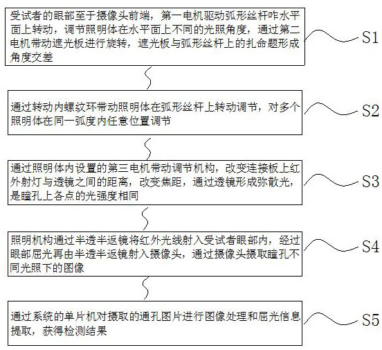
[0055] Such as Figure 10 As shown, a vision detection method for realizing adjustable light; including the following steps:
[0056] S1, the subject's eyes are at the front end of the camera, the first motor drives the arc-shaped screw to rotate on the horizontal plane to adjust the different irradiation angles of the illuminating body on the horizontal plane, and the second motor drives the visor to rotate. The illuminating body on the shaped screw forms an angle cross to block;
[0057] S2, by turning the internal thread ring to drive the lighting body to rotate and adjust on the arc-shaped screw rod, and adjust multiple lighting bodies at any position within the same arc;
[0058] S3, through the third motor installed in the lighting body to drive the adjustment mechanism, change the distance between the infrared spotlight on the connecting plate and the lens, thereby changing the focal length, forming diffuse light through the lens, so that the light intensity of each po...
Embodiment 2
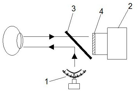
[0067] Such as figure 1 As shown, a vision detection system based on adjustable light; includes a camera 2, a half-return mirror 3 of the board head; a lighting mechanism 1 is arranged below the half-return mirror 3 of the board head, and the lighting mechanism 1 performs light adjustment, so The lighting mechanism 1 includes a base 11, a first motor 12 is arranged above the base 11, the output shaft of the first motor 12 is driven and connected with an arc-shaped screw rod 13, and the arc-shaped screw rod 13 is provided with a plurality of lighting bodies 15, The illuminating body 15 is provided with an infrared spotlight 1511 inside, and the infrared spotlight 1511 is connected with an adjustment mechanism, and the adjustment mechanism adjusts the beam angle, focal length, and beam distance of the infrared spotlight 1511. Illumination mechanism 1 injects infrared light into the human eye through the half-return mirror 3 of the board head, refracts the human eye, and then inj...
Embodiment 3
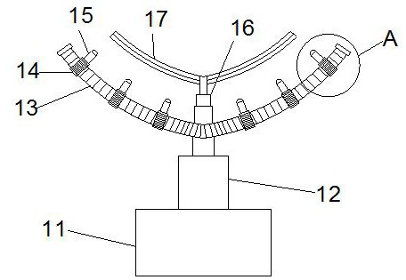
[0069] Such as Figure 2-5 , 7, on the basis of Embodiment 1, the output shaft of the first motor 12 is connected to the center of the arc-shaped screw 13, and the side of the arc-shaped screw 13 away from the first motor 12 is connected with a second The output shafts of the motor 16 and the second motor 16 are driven and connected with a shading plate 17, which is transparent or non-transparent, colored or colorless, and has a multi-layer structure.
[0070] One end of the illuminating body 15 provided on the arc screw 13 is provided with an internal thread ring 14, and the internal thread ring 14 is matched and rotationally connected with the arc screw 13; the arc screw 13 is connected with the first motor 12 The same number of illuminating bodies 15 are set on both sides of the center of the output shaft.
[0071] The central position of the outer wall of the internally threaded ring 14 is provided with a "I" type chute 19 along the circumferential direction, and the cent...
PUM
 Abstract
Description
Claims
Application Information
 - R&D
- Intellectual Property
- Life Sciences
- Materials
- Tech Scout
- Unparalleled Data Quality
- Higher Quality Content
- 60% Fewer Hallucinations
Browse by: Latest US Patents, China's latest patents, Technical Efficacy Thesaurus, Application Domain, Technology Topic, Popular Technical Reports.
© 2025 PatSnap. All rights reserved.Legal|Privacy policy|Modern Slavery Act Transparency Statement|Sitemap|About US| Contact US: help@patsnap.com


