Impact simulation method for Kelwet reticulated shell with roof panel
A simulation method and roof panel technology, applied in the field of structural impact, can solve the problems of difficult establishment of Kaiwitt spherical reticulated shell, low efficiency, and long reticulated shell impact simulation cycle, so as to improve the efficiency of numerical simulation operation and simplify the reticulated shell model , Reduce the effect of simulation operation cycle
- Summary
- Abstract
- Description
- Claims
- Application Information
AI Technical Summary
Problems solved by technology
Method used
Image
Examples
Embodiment 1
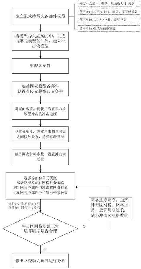
[0043] refer to figure 1 , is a flow chart of the impact simulation method for a Kaiwitt spherical reticulated shell with a roof panel adopted in the present invention, and is implemented according to the following steps:
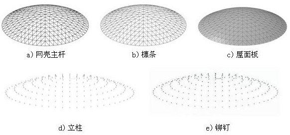
[0044] Step 1: Establish the main rod, purlin, column, rivet and roof panel model of Kaiwitt spherical reticulated shell;
[0045] Step 2: Use the "Import" function in the finite element analysis software ABAQUS to import the main rod, purlin, column, rivet and roof panel of the K8 reticulated shell established in step 1 into ABAQUS to generate each part of the finite element reticulated shell model, and at the same time establish Cylindrical impactor;
[0046] Step 3: Place the components in step 2 from the bottom to the top according to the order of the reticulated shell main rod, column, purlin, rivet, roof panel, and impact object, and complete the finite element model assembly;
[0047] Step 4: Connect the parts of the reticulated shell, set the thre...
Embodiment 2
[0057] According to the impact simulation method of a Kaiwitt reticulated shell with a roof panel described in Example 1, in the step 1, the model of the main rod, purlin, column, rivet, and roof panel of the Kaiwitt spherical reticulated shell is established, and the specific process yes,
[0058] 1.1) Determine the basic parameters of the Kaiwit spherical reticulated shell, and determine the span and height of the purlins and roof panels according to the geometric relationship between the main rod of the reticulated shell and the purlins and roof panels, and use the large-span spatial structure software MST to establish the main rods, purlins, roof panel model;
[0059] 1.2) Import the reticulated shell main rod-purlin, purlin-roof panel into AUTO-CAD, connect the reticulated shell main rod and purlin to generate the main rod, and connect the purlin and roof panel to generate rivets;
[0060] 1.3) Import the roof panel into Rhino software to generate the roof panel skin.
Embodiment 3
[0062] According to the impact simulation method of Kaiwit reticulated shell with roof panel described in Embodiment 1 or 2, in the step 1.1), the determination of the relationship between the main rod of the reticulated shell, the purlin, and the geometric dimension of the roof panel is as follows:
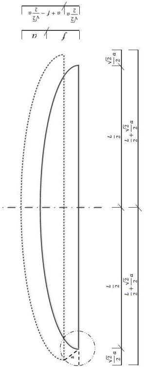
[0063] Purlins or roof spans L 1 , Yataka f 1 , determined by the following formula:
[0064]
[0065] In the formula, L is the span of the main pole of the reticulated shell, f is the vertical height of the main pole of the reticulated shell, a is the height of the column and rivets.
PUM
 Abstract
Description
Claims
Application Information
 - R&D
- Intellectual Property
- Life Sciences
- Materials
- Tech Scout
- Unparalleled Data Quality
- Higher Quality Content
- 60% Fewer Hallucinations
Browse by: Latest US Patents, China's latest patents, Technical Efficacy Thesaurus, Application Domain, Technology Topic, Popular Technical Reports.
© 2025 PatSnap. All rights reserved.Legal|Privacy policy|Modern Slavery Act Transparency Statement|Sitemap|About US| Contact US: help@patsnap.com


