In-furnace rotational flow fly ash reburning device
A fly ash reburning and internal swirl flow technology, which is applied in the direction of combustion method, combustion equipment, solid fuel combustion, etc., can solve the problem of low desulfurization efficiency, and achieve the effect of being conducive to fly ash reburning, uniform mixing and good effect
- Summary
- Abstract
- Description
- Claims
- Application Information
AI Technical Summary
Problems solved by technology
Method used
Image
Examples
Embodiment 1
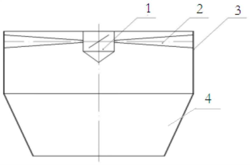
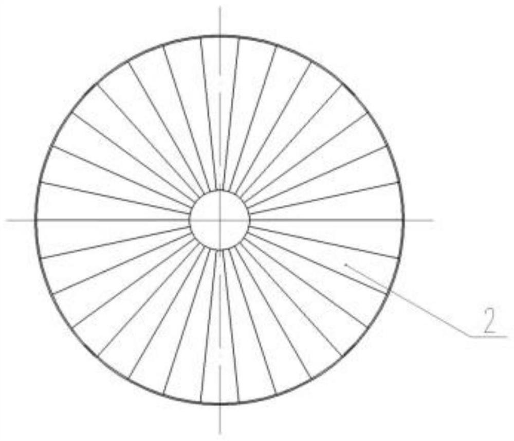
[0027] Such as figure 1 and figure 2 As shown, the present invention provides a furnace swirling fly ash reburning device, comprising: a cylinder 3 and a secondary air device, the air inlet of the secondary air device is sealed and connected to the air outlet of the cylinder 3, The air inlet of the cylinder 3 is sealed and connected with the air outlet of the slag pipe 4, and the cylinder 3 is provided with a blade 2, and the blade 2 is in the same direction as the flow direction of the fly ash coming out of the slag pipe 4. angle. The hot flue gas in the furnace carries unburned fly ash and coal particles, passes through the slag pipe 4, and enters the swirling fly ash reburning device in the furnace for reburning. This solution effectively solves the problem of low desulfurization efficiency in the furnace and improves the efficiency of desulfurization and denitrification in the furnace; on the other hand, the secondary air mixes evenly with fly ash, which is conducive to...
Embodiment 2
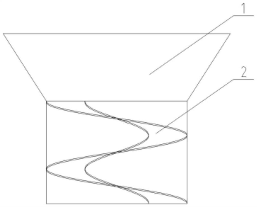
[0034] Such as image 3 As shown, the swirl fly ash reburning device in the furnace includes: a cylinder 3 and a secondary air device, the air inlet of the secondary air device is sealed and connected with the air outlet of the cylinder 3, and the air outlet of the cylinder 3 The air inlet is sealed and connected with the air outlet of the slag pipe 4, the cylinder 3 is provided with blades 2, and the blade 2 forms an angle with the flow direction of the fly ash coming out of the slag pipe 4, and the blades 2 is a spiral rising blade, the edge of the spiral rising blade is welded to the inner wall of the cylinder 3 . The spiral-rising blade is an integrated structure, which is easy to install and has a good effect on fully mixing and uniforming the mixed smoke.
[0035] As an optional solution, the blade 2 shown is made of steel plate. The stainless steel plate is convenient to be welded with the stainless steel cylinder 3, and has high strength and long service life.
[00...
Embodiment 3
[0039] Such as Figure 4 As shown, the swirl fly ash reburning device in the furnace includes: a cylinder 3 and a secondary air device, the air inlet of the secondary air device is sealed and connected with the air outlet of the cylinder 3, and the air outlet of the cylinder 3 The air inlet is sealed and connected with the air outlet of the slag pipe 4, the cylinder 3 is provided with blades 2, and the blade 2 forms an angle with the flow direction of the fly ash coming out of the slag pipe 4, and the blades 2 is dotted fragmented blades, a plurality of blades are sporadically dotted and welded on the inner wall, and spiral upward along the axis direction of the cylinder 3, the edge of the blade 2 is welded to the inner wall of the cylinder 3, which is convenient for installation, and The mixed flue gas has a better effect of thorough mixing and uniformity.
[0040]As an optional solution, the blade 2 shown is made of steel plate. The stainless steel plate is convenient to b...
PUM
 Abstract
Description
Claims
Application Information
 - R&D Engineer
- R&D Manager
- IP Professional
- Industry Leading Data Capabilities
- Powerful AI technology
- Patent DNA Extraction
Browse by: Latest US Patents, China's latest patents, Technical Efficacy Thesaurus, Application Domain, Technology Topic, Popular Technical Reports.
© 2024 PatSnap. All rights reserved.Legal|Privacy policy|Modern Slavery Act Transparency Statement|Sitemap|About US| Contact US: help@patsnap.com


