Coring device and coring method
A coring device and coring bit technology, which is applied in the direction of extracting undisturbed core devices, borehole/well valve devices, earthwork drilling and mining, etc., can solve problems such as ball valve stuck, and achieve the effect of accurate results and simple structure
- Summary
- Abstract
- Description
- Claims
- Application Information
AI Technical Summary
Problems solved by technology
Method used
Image


Examples
Embodiment 1
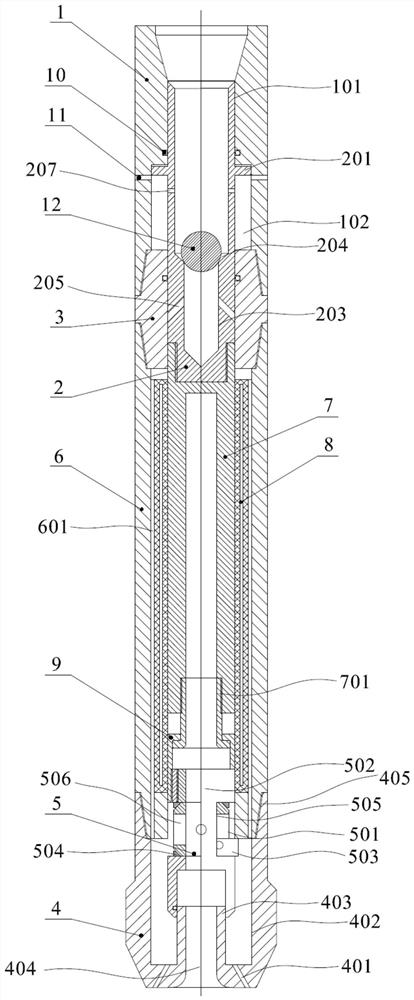
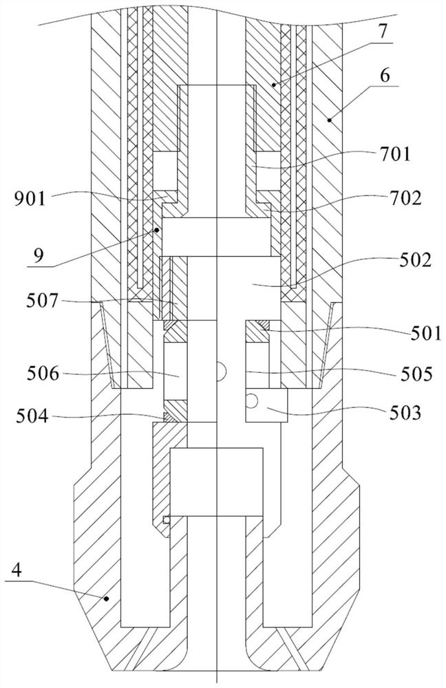
[0033] figure 1 It is a schematic diagram of the state of the coring device opening the ball valve, figure 2 It is a schematic diagram of the state of closing the ball valve of the coring device, image 3 yes figure 2 Enlarged view of one end of the core bit in the coring device, see Figure 1-Figure 3 As shown, the coring device includes an upper connection button 1 , a coring outer cylinder 6 and a coring drill 4 connected in sequence. The upper link 1 is used to connect a power device to provide drilling power. The upper connecting button has an axially arranged connecting button inner hole 101, the connecting button inner hole 101 of the upper connecting button 1, the inner hole of the coring outer cylinder 6 and the drill bit inner hole 402 of the coring drill bit 4 connected to form the first shaft hole. The core drill 4 is provided with a drill inner hole 402 , and the bottom surface of the drill inner hole 402 is provided with a core hole 404 , and one end of th...
Embodiment 2
[0035] The difference between the coring device in embodiment 1 and the coring device in embodiment 2 lies in the lifting mechanism. see Figure 1-Figure 3 As shown, the lifting mechanism includes a protruding ring 201 arranged on the outer wall of the differential lifting rod 2, an annular groove 102 is opened on the inner wall of the inner hole 101 of the buckle, and the outer diameter of the protruding ring 201 is consistent with the The diameters of the ring grooves 102 are equal. The protruding ring 201 is set in the annular groove 102, and the differential lifting rod 2 is provided with a second communication hole 207, and the second communication hole 207 is located on the protruding ring 201 close to the core bit 4 On one side, the second communication hole 207 communicates with the buckle inner hole 101, the side wall of the ring groove 102 is provided with a second drain hole 11, and the second drain hole 11 is located in the convex ring 201 away from the side of t...
Embodiment 3
[0039] see Figure 1-Figure 3 As shown, on the basis of Example 2, the inner wall of the coring outer cylinder 6 is provided with a vacuum insulation sleeve 8 to further heat-insulate the coring inner cylinder 7 . The upper adapter 1 is connected to the coring outer cylinder 6 through a connecting head 3 . The two ends of the connecting head 3 form a tapered structure, and the two ends of the coring outer cylinder 6 are provided with tapered holes to be threadedly connected with the connecting head 3 . The connecting groove 206 is opened on the connecting head 3 and the coring outer cylinder 6 , or the section of the connecting head 3 and the bottom surface of the taper hole of the coring outer cylinder 6 are spaced to form the connecting groove 206 . The coring outer cylinder 6 is threadedly connected to the core bit 4 . The chamfering of the mouth of the drill inner hole 402 forms a tapered hole structure 404, the two ends of the coring outer cylinder 6 are tapered, and th...
PUM
 Abstract
Description
Claims
Application Information
 - R&D
- Intellectual Property
- Life Sciences
- Materials
- Tech Scout
- Unparalleled Data Quality
- Higher Quality Content
- 60% Fewer Hallucinations
Browse by: Latest US Patents, China's latest patents, Technical Efficacy Thesaurus, Application Domain, Technology Topic, Popular Technical Reports.
© 2025 PatSnap. All rights reserved.Legal|Privacy policy|Modern Slavery Act Transparency Statement|Sitemap|About US| Contact US: help@patsnap.com