Constructional column structure and pouring method

A technology for constructing columns and pouring pipes, which is applied in building structures, buildings, building components, etc., can solve problems such as cracks, troublesome construction procedures, and secondary damage to structural columns.

Inactive Publication Date: 2021-09-07
浙江德为建材科技股份有限公司
View PDF3 Cites 0 Cited by
  • Summary
  • Abstract
  • Description
  • Claims
  • Application Information

AI Technical Summary

Problems solved by technology

When there is already a built-up beam at the top of the structural column, a feed inlet will be provided on the side of the structural column formwork (such as figure 1 shown), but the conventional pouring method of the structural column generally adopts the method of pouring the concrete of the structural column, and the feed inlet should also be fully poured. In this way, after the pouring is completed, a beveled horn protruding from the wall will be formed on the top of the structural column. The corbel, the corbel can only be removed as a whole after the concrete is fully formed, which not only limits the construction speed and efficiency, consumes manpower and material resources, but also causes roughness and cracks on the surface of the structural column when the corbel is knocked out in the later stage. The secondary damage of the structural column affects the construction quality of the structural column; the other is to pour a small section of concrete at the end of the structural column, and then perform secondary pouring
The traditional pouring process is not only troublesome in the construction process, but also requires chiseling or secondary construction of the structure in the later stage, which not only increases labor and materials, but also cannot guarantee the quality well

Method used


Image

  • Constructional column structure and pouring method
  • Constructional column structure and pouring method

Examples


Embodiment Construction

[0023] refer to Figure 1 to Figure 2 The specific implementation of a structural column structure and pouring method of the present invention will be further described.

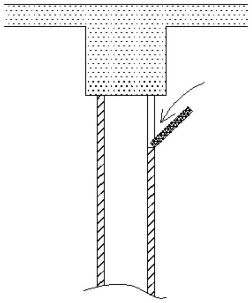
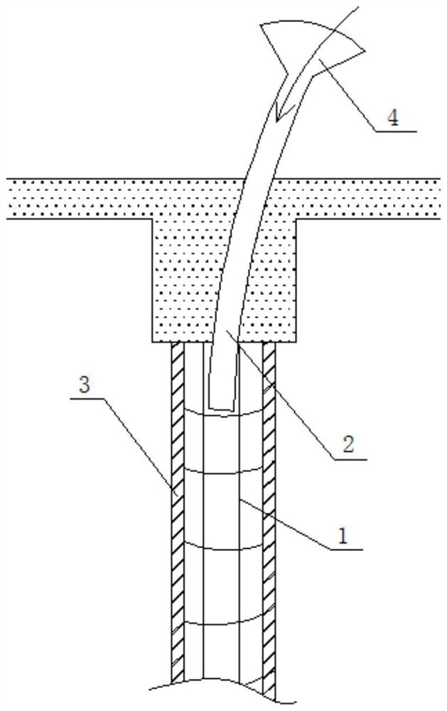
[0024] A construction column 1 structure includes a column body composed of several steel bars and stirrups, a pouring formwork 3 is arranged on the outside of the column body, and a pouring pipe 2 is arranged on the top of the column body.

[0025] The hollow pouring pipe 2 is set on the top of the structural column 1, pre-buried in the upper beam and the upper end is exposed to the beam. The shape of the pouring pipe 2 can be set according to the density of the steel bars in the structural column 1. Generally, the diameter is set to 50- 80mm, if the steel bars are too dense, the pouring pipe 2 can be set as a flat shape, which is convenient for extending into the column. During construction, the pouring liquid can be poured directly from the upper pouring pipe 2. The construction column 1 of the present i...


PUM


Abstract

The invention discloses a constructional column structure and a pouring method. The constructional column structure comprises a column body composed of a plurality of steel bars and stirrups, the outer side of the column body is provided with a pouring formwork, and the top of the column body is provided with a pouring pipe. The pouring pipe is pre-buried at the top end of the constructional column, pouring is conducted from top to bottom during construction, and labor is saved during operation; a pouring funnel does not need to be reserved on the top of the side pouring formwork, formwork matching is simple, and labor and materials are saved; the reserved pouring pipe is convenient to install and low in cost; redundant inclined bucket concrete does not need to be chiseled off after forming, so that labor and materials are saved; and the pouring quality is better.

Description

technical field [0001] The invention relates to the technical field of building construction, and more specifically relates to a structural column structure and a pouring method. Background technique [0002] In order to enhance the integrity and stability of the building, reinforced concrete structural columns are generally set in the walls of multi-storey buildings, and are connected with ring beams on each floor to form a space frame capable of resisting bending and shearing. Setting structural columns is An effective measure to prevent house collapse. At present, when pouring the structural column, the structural column template is implanted in the wall, and a concrete pouring opening is reserved at the top, and the pouring opening and the structural column are integrally poured. When there is already a built-up beam at the top of the structural column, a feed inlet will be provided on the side of the structural column formwork (such as figure 1 shown), but the convent...

Claims


Application Information

Patent Timeline
Patent Type & Authority Applications(China)
IPC IPC(8): E04B2/68E04G21/04
CPCE04B2/68E04G21/0472
Inventor 林光明
Owner 浙江德为建材科技股份有限公司
Why Eureka
Try Eureka