Lathe with high machining precision

A technology of processing precision and lathe, which is applied in the direction of metal processing equipment, turning equipment, turning equipment, etc., can solve the problems of reducing flange processing precision and stability, so as to reduce the probability of slippage, improve stability and improve efficiency Effect

Active Publication Date: 2021-09-07
济南泰康锻造股份有限公司
View PDF14 Cites 3 Cited by
  • Summary
  • Abstract
  • Description
  • Claims
  • Application Information

AI Technical Summary

Problems solved by technology

[0005] In view of the above-mentioned related technologies, the inventor believes that it may be necessary to move the slider when processing flanges of different types so that the top cone can abut against the end face of the flange blank. When moving the slider, the operator needs to Adjust multiple sliders separately, and the adjusted top cone may be unevenly distributed on the three-jaw chuck, so the stability of the top cone supporting the flange blank will be reduced, thereby reducing the machining accuracy of the flange

Method used


Image

  • Lathe with high machining precision
  • Lathe with high machining precision
  • Lathe with high machining precision

Examples


Embodiment Construction

[0037] The following is attached Figure 1-5 The application is described in further detail.

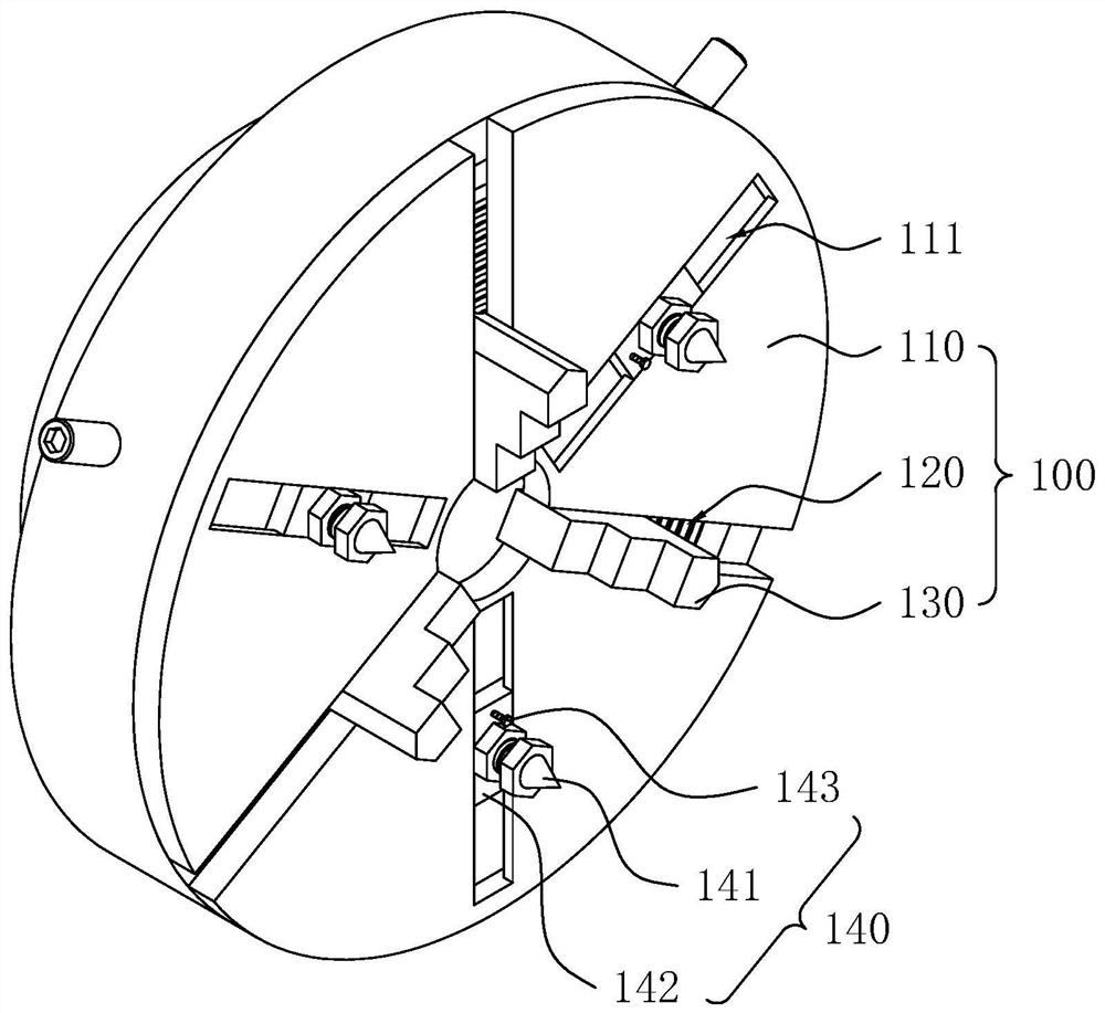
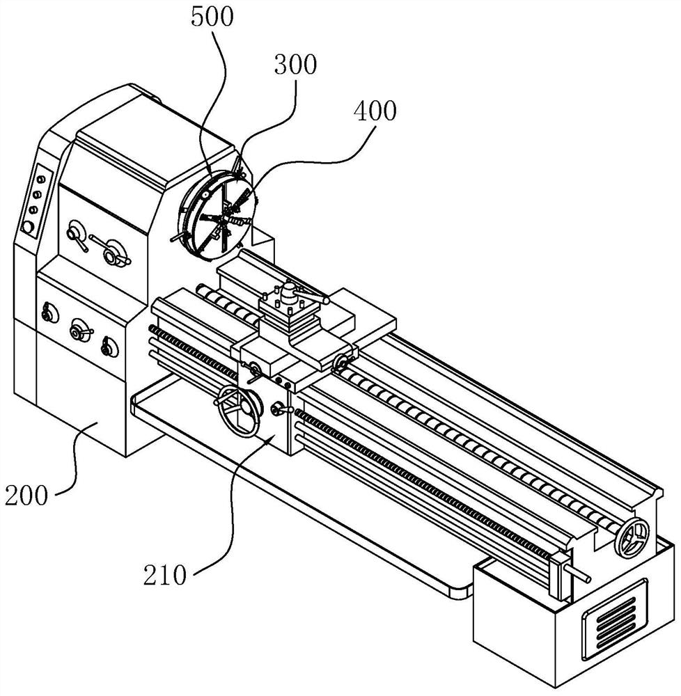
[0038] refer to figure 1 , in the related art, a three-jaw chuck 100 with a positioning assembly 140 includes a disk body 110 , a spiral disk 120 and three jaws 130 , and the positioning assembly 140 is disposed on the disk body 110 of the three-jaw chuck 100 . The positioning assembly 140 includes three sliders 142, three top cones 141 and three locking bolts 143. The disk body 110 is provided with three sliding slots 111 along its radial direction, and the three sliding grooves 111 are evenly distributed in the circumferential direction of the disk body 110. It is provided that one slide block 142 is correspondingly arranged in one slide groove 111 , and one top cone 141 is correspondingly threaded on one slide block 142 . The locking bolt 143 is threadedly connected to the slider 142, and the end of the locking bolt 143 far away from its own bolt head passes through the slider 1...


PUM


Abstract

The invention relates to a lathe with high machining precision, and relates to the technical field of flange machining. The lathe comprises a rack, wherein a main shaft and a turning mechanism used for cutting a flange blank are arranged on the rack, a three-jaw chuck is arranged on the main shaft, a positioning assembly is arranged on a chuck body of the three-jaw chuck, the positioning assembly comprises a plurality of sliding blocks and tip cones with the same number as the sliding blocks, the sliding blocks are in sliding connection with the chuck body in the radial direction of the chuck body, the sliding blocks can be meshed with a spiral disc, and the tip cones are arranged on the sliding blocks; and a switching mechanism is further arranged on the chuck body, the switching mechanism is used for controlling the sliding blocks and clamping jaws on the three-jaw chuck, so that the sliding blocks are meshed with the spiral disc or the clamping jaws are meshed with the spiral disc. According to the lathe, when an operator rotates the spiral disc, the sliding blocks can synchronously slide, so that the tip cones can be distributed on the three-jaw chuck more uniformly, and then the stability of the tip cones when the tip cones support the flange blank is improved.

Description

technical field [0001] The present application relates to the field of flange machining, in particular to a lathe with high machining accuracy. Background technique [0002] Flanges are the interconnected parts between shafts and can also be used for the connection between pipe ends, the connection between the inlet and outlet of equipment, and the connection between two equipment. Most of the flanges need to be heated, forging, ring rolling, turning and drilling during processing. During turning, it is divided into two steps: turning the inner ring and turning the outer ring. S1, turning the inner ring, using a fixture to hold the outer ring of the flange blank, and then turning the inner ring of the flange and one of its end faces; S2, turning the outer ring, using a fixture to hold the inner ring of the flange blank, The outer ring of the flange and the other end face are then turned. [0003] refer to figure 1 At present, in order to improve the stability of clamping ...

Claims


Application Information

Patent Timeline
Patent Type & Authority Applications(China)
IPC IPC(8): B23B31/02B23B31/163B23B5/00
CPCB23B31/16004B23B5/00B23B31/02
Inventor 王震韩绪庆李春李咸通李志斗
Owner 济南泰康锻造股份有限公司
Why Eureka
Try Eureka