Deep processing equipment for hydraulic modified asphalt

A modified asphalt and hydraulic technology, which is applied in the field of asphalt deep processing, can solve problems such as inability to mix asphalt uniformly, inconvenient addition of mixture, and poor quality of asphalt, and achieve the effects of preventing clogging, excellent asphalt quality, and uniform and rapid mixing

Inactive Publication Date: 2021-09-07
左重全
View PDF12 Cites 1 Cited by
  • Summary
  • Abstract
  • Description
  • Claims
  • Application Information

AI Technical Summary

Problems solved by technology

[0006] However, in the technical scheme given above, high-temperature asphalt will generate air bubbles during the deep processing of asphalt, and the continuously accumulated air bubbles will seal the upper end of the processing tank, making it inconvenient to add the mixture during asphalt processing to the inside of the processing tank. , and in the process of asphalt processing, the material body added to the asphalt cannot be mixed evenly with the asphalt, so that the quality of the asphalt after deep processing is poor, so a device is urgently needed to solve the above problems

Method used


Image

  • Deep processing equipment for hydraulic modified asphalt
  • Deep processing equipment for hydraulic modified asphalt
  • Deep processing equipment for hydraulic modified asphalt

Examples


Embodiment 1

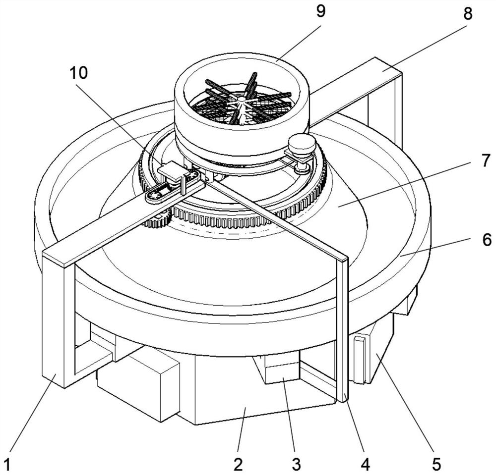
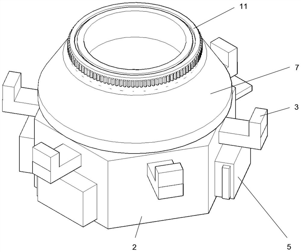
[0036] see figure 1 An embodiment provided by the present invention: a deep processing equipment for hydraulically modified asphalt, including a first fixed support frame 1, a processing pipe body 2, an L-shaped support fixed plate 3, a first connecting frame 4, and a discharge control valve 5. Storage collecting tray 6, stirring and mixing tank 7, second fixed support frame 8, mixing and cleaning mechanism 9 and drive control device 10, stirring and mixing tank 7 is rotatably installed inside the processing pipe body 2, and storing and storing collecting tray 6 is fixed Installed on the upper end of the stirring mixing tank 7, the L-shaped support and fixing plate 3 is evenly fixed and installed between the processing pipe body 2 and the storage collection plate 6, and the discharge control valve 5 is evenly fixed and installed on the middle part of the side end surface of the processing pipe body 2, The first fixed support frame 1 is fixedly installed between the drive contr...

Embodiment 2

[0047] On the basis of Example 1, such as Figure 10 As shown, the edge of the storage collection tray 6 is uniformly fixedly inserted with a discharge pipe 37, and the outer ends of the discharge pipe 37 are threaded and installed with a sealing plug 36, and the discharge pipe 37 is provided with six, and the discharge pipe 37 distributed in a circle.

[0048] When implementing the present embodiment, because the edge of the storage collection tray 6 is uniformly fixedly inserted with a discharge pipe 37, the outer ends of the discharge pipe 37 are threaded and equipped with a sealing plug 36, and the discharge pipe 37 is provided with six, And the discharge pipe 37 is circularly distributed, so the high-temperature asphalt bubbles that continuously flow into the storage collection pan 6 continue to flow out through the discharge pipe 37 before solidification, thereby facilitating the collection of the asphalt collected in the storage collection pan 6. Recycle and reuse.


PUM


Abstract

The invention discloses deep processing equipment for hydraulic engineering modified asphalt, and the equipment comprises a first fixed supporting frame, a processing pipe body, an L-shaped supporting fixing plate, a first connecting frame, discharging control valves, a storage and collection disc, a stirring and mixing tank, a second fixed supporting frame, a mixing and cleaning mechanism and a driving control device. The stirring and mixing tank is rotatably mounted in the processing pipe body, the storage and collection disc is fixedly mounted at the upper end of the stirring and mixing tank, the L-shaped supporting and fixing plates are uniformly and fixedly mounted between the processing pipe body and the storage and collection disc, and the discharging control valves are uniformly and fixedly mounted in the middle of the side end face of the processing pipe body. The first fixed support frame is fixedly mounted between the driving control device and the processing pipe body; the second fixed supporting frame is fixedly mounted between the mixing and cleaning mechanism and the processing pipe body, and a rotary adjusting gear ring is fixedly mounted at the upper end of the stirring and mixing tank. In the use process, the added material body and asphalt can be fully mixed.

Description

technical field [0001] The invention relates to the technical field of asphalt deep processing, in particular to deep processing equipment for hydraulically modified asphalt. Background technique [0002] Modified asphalt is the addition of external additives (modifiers) such as rubber, resin, high molecular polymer, ground rubber powder or other fillers, or taking measures such as mild oxidation of asphalt to make asphalt or asphalt mixture The performance of the asphalt binder can be improved. [0003] According to Chinese Patent No. CN201620921786.5, the utility model discloses a modified asphalt batching production and dosing device, including a circulation outlet arranged in the middle of the side wall of the reactor and a circulation inlet issued from the side wall, the circulation outlet and the circulation The inlets are sequentially connected through elbows, high-mix tanks, standpipes and horizontal pipes. The high-mix tanks are oblate and installed horizontally. T...

Claims


Application Information

Patent Timeline
Patent Type & Authority Applications(China)
IPC IPC(8): B01F13/10
Inventor 左重全何文刚
Owner 左重全
Why Eureka
Try Eureka