A kind of ups emergency power supply of industrial electric power and power supply method thereof
A technology of emergency power supply and electric power, applied in emergency power supply arrangement, battery circuit device, circuit, etc., can solve the problems of damage to the original power supply of emergency power supply, unfavorable emergency power supply power supply, easy sparks in connection, etc., to reduce the probability of breakage and easy to solve. Damage, short-circuit prevention effect
- Summary
- Abstract
- Description
- Claims
- Application Information
AI Technical Summary
Problems solved by technology
Method used
Image
Examples
Embodiment 1
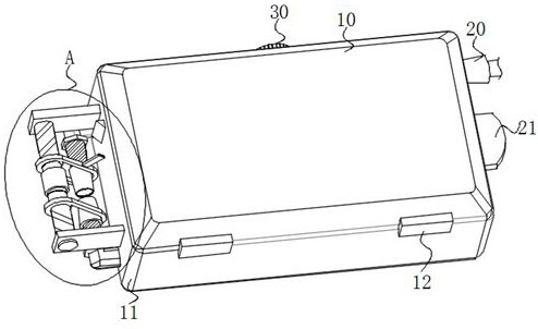
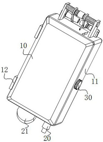
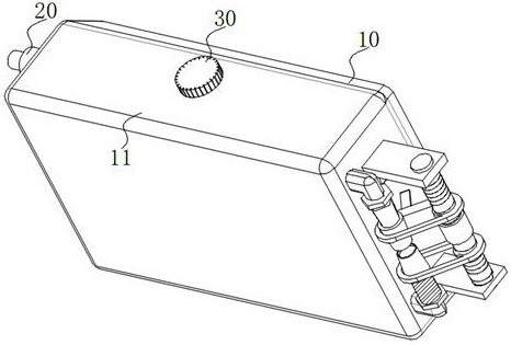
[0040] Embodiment 1: According to Figure 1-Figure 6 with Figure 11 As shown, a UPS emergency power supply for industrial power includes an upper casing 10, a lower casing 11, and a connection block 12. A battery block 111 is installed inside the lower casing 11, and the left side of the battery block 111 is front and rear. Both terminals are fixedly connected with a terminal block 14, and the outer surface of the terminal block 14 is fixedly connected with a hexagonal block 144, which is a common spacer for an existing terminal post, and the two terminal blocks 14 both extend to the lower casing 11 The outer side of the terminal block 14 at the front end is fixedly connected with a positive terminal 141, and the end of the terminal block 14 at the rear end is fixedly connected with a negative terminal 145, and the hexagonal block 144 is connected to the corresponding positive terminal 141 is in contact with the end of the negative pole terminal 145, and the setting of the h...
Embodiment 2
[0042] Embodiment 2: On the basis of Embodiment 1, a control switch 15 is installed on the left rear portion of the lower housing 11, and the end of the slider 132 close to the control switch 15 is fixedly connected with a push block 133. The switch 15 is rotatably connected with the lower housing 11. The material of the end of the push block 133 away from the slider 132 is made of rubber, and the end of the push block 133 in contact with the control switch 15 is made of rubber to protect the control switch 15. The push block 133 can push the control switch 15 during the sliding process, so that the push block 133 can push the control switch 15 to realize the power supply control of the emergency power supply, and the control switch 15 of the emergency power supply and the positive pole terminal 141 and the negative pole The movement distance of the cover block 142 on the terminal 145 is related, so that the control switch 15 is in the state of controlling the emergency power s...
Embodiment 3
[0044] Embodiment 3: on the basis of embodiment 1 and embodiment 2, according to figure 1 , Figure 9 with Figure 15 As mentioned above, the right side of the lower case 11 is fixedly connected with a hollow column 20, and the right side of the battery block 111 is equipped with a power line, and the power line extends to the outside of the lower case 11 through the hollow column 20, so The hollow column 20 is designed in the shape of a truncated cone. The hollow column 20 arranged in the shape of a truncated cone is a hollow structure. The side of the hollow column 20 arranged in the shape of a truncated cone is in contact with the lower casing 11. Therefore, the power cord extends to the lower casing 11. After the outer side, the active area of the power line increases on the basis of achieving stability, which can effectively prevent the power line from breaking, reduce the short circuit phenomenon of the emergency power supply, and facilitate the power supply of the em...
PUM
 Abstract
Description
Claims
Application Information
 - R&D
- Intellectual Property
- Life Sciences
- Materials
- Tech Scout
- Unparalleled Data Quality
- Higher Quality Content
- 60% Fewer Hallucinations
Browse by: Latest US Patents, China's latest patents, Technical Efficacy Thesaurus, Application Domain, Technology Topic, Popular Technical Reports.
© 2025 PatSnap. All rights reserved.Legal|Privacy policy|Modern Slavery Act Transparency Statement|Sitemap|About US| Contact US: help@patsnap.com


