Pile foundation safety device for constructional engineering
A safety device and construction engineering technology, applied in the direction of construction, building components, protection devices, etc., can solve the problems of steel sheet pile damage, large manpower and material resources, inaccurate positioning, etc., to improve the efficiency of the project, reduce the physical burden, avoid The effect of construction work
- Summary
- Abstract
- Description
- Claims
- Application Information
AI Technical Summary
Problems solved by technology
Method used
Image
Examples
Embodiment 1
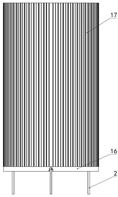
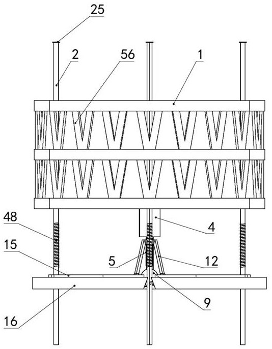
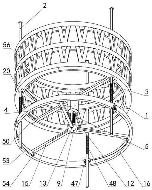
[0034] Embodiment 1, the technical solution it solves is a pile foundation safety device for construction engineering, including a plurality of vertical rings 1 and a plurality of vertical support columns 2, and the plurality of rings 1 are evenly distributed vertically , a plurality of support columns 2 are evenly distributed along the circumferential direction of the ring 1, any support column 2 slides through the plurality of rings 1 in sequence in the vertical direction, and there are multiple clamping mechanisms evenly distributed on the upper circumference of the ring 1, and multiple clamping mechanisms The mechanism corresponds to a plurality of support columns 2 one by one, and the sliding of the support column 2 on the ring 1 is limited by the clamping mechanism; the lowermost ring 1 among the plurality of rings 1 is connected with the first support rod 3 , and the second A support rod 3 is arranged along the front and back directions, and a vertical cylindrical airtig...
Embodiment 2
[0035] Embodiment 2. On the basis of Embodiment 1, the clamping mechanism includes a snap ring 18, a first wedge block 19, a first through hole 20, and a second sliding groove 21. The first through hole 20 vertically runs through the circle The ring 1, the support column 2 pass through the first through hole 20, the snap ring 18 is sleeved on the support post 2, the snap ring 18 is located in the first through hole 20, and the diameter of the snap ring 18 is slightly smaller than the diameter of the first through hole 20 , the second chute 21 is opened in the ring 1, and the end of the second chute 21 close to the snap ring 18 communicates with the first through hole 20; the end of the first wedge block 19 is close to the snap ring 18, and the end of the first wedge block 19 The wedge-shaped end is close to the snap ring 18, and the first wedge-shaped block 19 is placed above the snap ring 18. A first spring 22 is connected between the end of the first wedge-shaped block 19 awa...
Embodiment 3
[0036] Embodiment 3, on the basis of Embodiment 2, the upper end of the support column 2 is covered with a solid torus 25, the shape and size of the torus 25 are the same as that of the snap ring 18, and the torus 25 is coaxial with a plurality of The distance between the uppermost snap rings 18 in the snap rings 18 is A, the distance between the coaxial adjacent snap rings 18 is B, and the value of A is the same as the value of B; the first wedge block 19 is far away from the snap rings One end of 18 is connected with a first piston 26, and the first piston 26 is sealed and slid in the second chute 21, and the end of the slider 23 away from the snap ring 18 is connected with a second piston 27 via a rod, and the second piston 27 is in the second sliding groove. Seal sliding in the groove 21; the second chute 21 is connected with a partition 28, the partition 28 is located between the first piston 26 and the second piston 27, the second chute 21 is connected with a second magne...
PUM
 Abstract
Description
Claims
Application Information
 - Generate Ideas
- Intellectual Property
- Life Sciences
- Materials
- Tech Scout
- Unparalleled Data Quality
- Higher Quality Content
- 60% Fewer Hallucinations
Browse by: Latest US Patents, China's latest patents, Technical Efficacy Thesaurus, Application Domain, Technology Topic, Popular Technical Reports.
© 2025 PatSnap. All rights reserved.Legal|Privacy policy|Modern Slavery Act Transparency Statement|Sitemap|About US| Contact US: help@patsnap.com


