Eureka AIR delivers breakthrough ideas for toughest innovation challenges, trusted by R&D personnel around the world.

Lifter assembly and system for removing highway or railway bridges

a technology for lifting and removing railway bridges, applied in bridges, transportation and packaging, cranes, etc., can solve problems such as aging or corrosion of steel bridges, and achieve the effects of convenient handling, simple structure and lightweight weigh

Active Publication Date: 2019-03-21
BRIDGINNOVA INC
View PDF0 Cites 5 Cited by
  • Summary
  • Abstract
  • Description
  • Claims
  • Application Information

AI Technical Summary

Benefits of technology

The present invention is a lifter assembly that can be used to remove or replace highway or railway bridges. It has a simple structure and is lightweight. It can be easily and efficiently transported to a desired location by switching between rail wheels and traveling wheels. Additionally, it can adapt to different bridge spans with varying widths and is easy to handle.

Problems solved by technology

Inevitably, some of the steel bridges shown signs of aging or corrosion.

Method used


Image

  • Lifter assembly and system for removing highway or railway bridges
  • Lifter assembly and system for removing highway or railway bridges
  • Lifter assembly and system for removing highway or railway bridges

Examples


Embodiment Construction

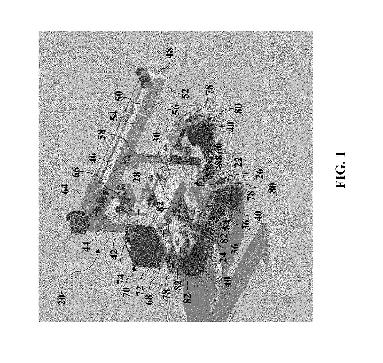
[0019]Referring to the Figures, wherein like numerals indicate corresponding parts throughout the several views, it is one aspect of the present invention to provide a lifter assembly 20 for removing or replacing highway or railway bridges. The lifter assembly 20 constructed in accordance with one embodiment of the present invention is generally shown in FIG. 1.

[0020]As illustrated in FIG. 1, the lifter assembly 20 includes a base 22, having a generally H-shape. The base 22 includes a first member 24 and a second member 26 disposed parallel to and spaced from one another. An intermediate member 28 extends perpendicularly between the first member 24 and the second member 26 to connect the first member 24 with the second member 26 for receiving a bridge span 30. The base 22 has a top surface 32 for receiving the bridge span 30 and a bottom surface 34 disposed on an opposite side of the top surface 32.

[0021]As best shown in FIGS. 2 and 3, the first member 24 and the second member 26 ea...


PUM


Abstract

A lifter assembly includes a base having a top and a bottom surface. Connectors are attached to the base extending outwardly from the bottom surface. Each of the connectors includes at least one rail wheel rotatably attached thereto. The base includes traveling wheels rotatably attached thereto. A post is attached to the base extending outwardly from the top surface to a distal end. An arm is disposed on the distal end, rotatably attached to the post, extending outwardly to a terminal end. A support is movably attached to the arm and extends outwardly to a support end. A trolley is slidably disposed on the arm and movable along the arm between the terminal end and the post. Each of the traveling wheels includes a leg pivotably attached to the base connecting the traveling wheel to the base and move the traveling wheel between a transport and a storage position.

Description

CROSS REFERENCE TO RELATED APPLICATION[0001]This application claims the benefit of U.S. Provisional Patent Application Ser. No. 62 / 561,411 filed on Sep. 21, 2017, the entire disclosure of which is incorporated herein by reference in its entirety.BACKGROUND OF THE INVENTION1. Field of the Invention[0002]The present invention generally relates to a lifter assembly and a system for removing or replacing highway or railway bridges.2. Description of the Prior Art[0003]Some steel bridges used in railway have been in use for nearly a century. Inevitably, some of the steel bridges shown signs of aging or corrosion. In order to guarantee safety use of the steel bridges, the bridges showing serious damages or corrosions need to be replaced or removed. As time goes by, the workload of replacing or removing bridges becomes greater and machines have been used to provide an efficient way of removing the bridges.[0004]One such a machine is disclosed in U.S. Pat. No. 7,470,586. The machine includes...

Claims


Application Information

Patent Timeline
Patent Type & Authority Applications(United States)
IPC IPC(8): E01D21/00B66C23/78B60F1/04B66C23/36B66C9/00B66C23/50
CPCE01D21/00B66C23/78B60F1/043B66C23/36B66C9/00B66C23/50B66C2700/0378B66C2700/035B66C2700/0342B66C2700/0371B66C23/365
Inventor LIU, YABINPAN, DACHEN, WEI
Owner BRIDGINNOVA INC
Why Eureka
Eureka Blog
Learn More