
Full-automatic cooker

A cooking machine, fully automatic technology, applied in household heating, heating methods, lighting and heating equipment, etc., can solve the problems of energy saving, unsanitary, environmental protection, etc., to ensure the stir-frying effect, reduce oil stains, and improve taste Effect

Active Publication Date: 2021-09-03
袁晨晖
View PDF8 Cites 0 Cited by
  • Summary
  • Abstract
  • Description
  • Claims
  • Application Information

AI Technical Summary

Problems solved by technology

In the prior art, when the cooking machine is stir-frying, the stirring of the cooking knife is directly driven by the driving device, so that the stirring of the cooking knife is always at a relatively fast speed, which is quite different from the frequency of swinging the shovel during actual cooking. Then affect the mouthfeel of cooking, and the cooking fumes of the existing cooking machine are directly discharged from the casing, and then cause the room to be full of cooking fumes, so the existing cooking machines have the problems of not being energy-saving, environmentally friendly, unhygienic, and unhealthy; People designed a fully automatic cooking machine, which uses the full fit of the heating tube and the outer wall of the pot, and at the same time exhausts the smoke through the exhaust assembly, and the heat collection tube re-applies the heat in the smoke to the pot body. In order to realize the repeated utilization of heat, and through the degreasing treatment of the exhaust components, the oil stains in the exhausted flue gas are greatly reduced, thereby ensuring that the indoor air environment has no irritating odor; and the rotation of the stirring rod can be quickly Good simulation of the stir-frying rules during manual cooking in reality, to ensure the stir-frying effect of the stir-frying knife and improve the taste of the dishes

Method used


Image

  • Full-automatic cooker
  • Full-automatic cooker
  • Full-automatic cooker

Examples


Embodiment 1

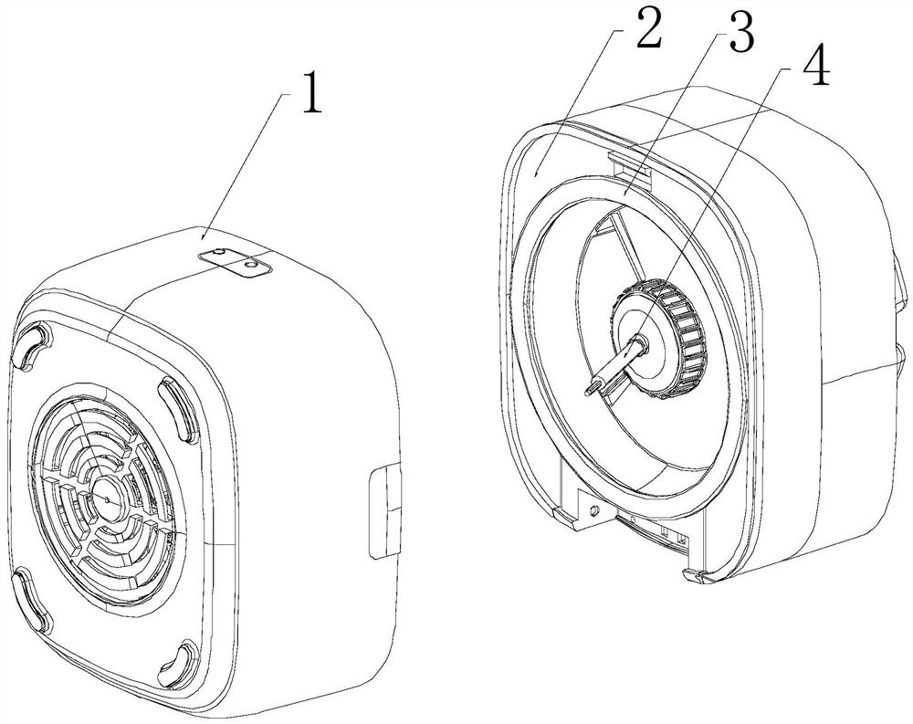
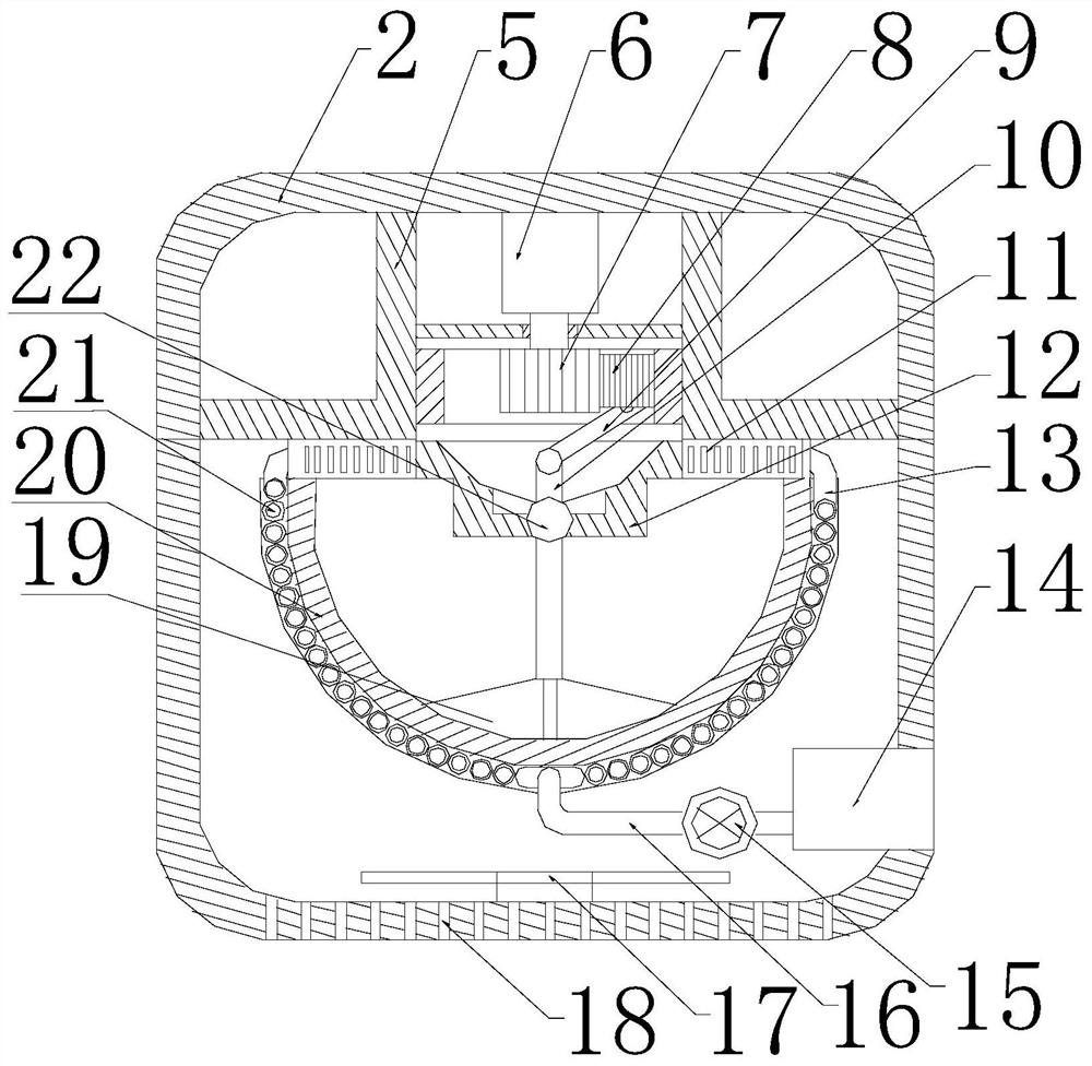
[0026] Such as Figure 1~5 As shown, this embodiment includes an upper casing 2 and a lower casing 1 hinged to each other, a sealing ring 3 is provided on the inner wall of the upper casing 2, and a fixed cavity 5 is provided in the upper casing 2 to fix The cavity 5 is provided with a motor 6 and an internal gear. The output end of the motor 6 is provided with a main gear 7. The main gear 7 meshes with the internal gear through a secondary gear 8. A connecting rod 9 is hingedly arranged on the end face of the secondary gear 8. The lower end of the fixed cavity 5 is provided with a base 12, and a spherical cavity is provided on the lower end surface of the base 12, and a ball head 22 cooperating with it is provided in the spherical cavity, and the upper end and the lower end of the ball head 22 respectively protrude from the spherical cavity, The upper end of the ball head 22 is provided with a linkage rod 10 hinged with the connecting rod 9, the lower end of the ball head 22 ...

Embodiment 2

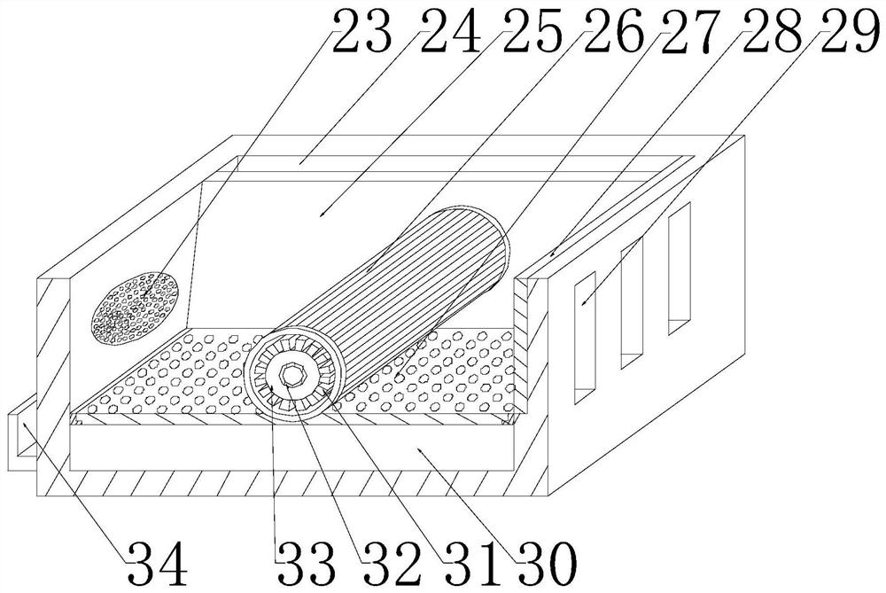
[0032] Such as Figure 1~5 As shown, after using this embodiment for a period of time, a certain amount of oil stains will accumulate in the exhaust cavity, which needs to be cleaned regularly. The cleaning pipe 32 is placed in the middle of the rotating shaft 33, and when the smoke is exhausted, the cleaning pipe 32 It is in a closed state, that is, no cleaning liquid is injected. When the motor 6 is stopped, the liquid injection port of the cleaning pipe 32 located in the adjustment chamber is opened, and the cleaning liquid flowing at a high speed is injected into the cleaning pipe 32, and the cleaning liquid passes through the liquid outlet. 39 is ejected outward, and because the roller 26 is set for rotation, the ejected cleaning liquid can directly act on the roller 26, and the roller 26 can be driven by the ejected cleaning liquid, thereby realizing the rotation of the roller 26 and rotating The roller 26 can sprinkle the cleaning liquid on the inner wall of the trapezo...

Embodiment 3

[0035] Such as figure 2 with Figure 5 As shown, the interior of the liquid storage cylinder 14 in this embodiment is provided with a cavity, the liquid outlet of the pump 15 communicates with the interior of the cavity, and a baffle 35 is provided above the inner wall of the cavity, and the baffle 35 is arranged along the row. The air direction is arranged obliquely from top to bottom, and there are a plurality of air outlets 36 on the side wall of the liquid storage cylinder 14 facing away from the suction and discharge pipe 13, and a liquid discharge port is opened on the side wall of the liquid storage cylinder 14. The liquid port is located below the air discharge port 36, and a plug 37 is provided on the liquid discharge port. After entering the tail pipe 16 from the heat collecting tube, the tail pipe 16 has a certain length after being folded, so that the water vapor in the flue gas can be gradually liquefied, and when the used flue gas enters the cavity through the ...


PUM


Abstract

The invention discloses a full-automatic cooker which comprises an upper shell and a lower shell. A motor and an inner gear are arranged in a fixed cavity, a connecting rod is hinged to the end surface of an auxiliary gear, a base is arranged at the lower end of the fixed cavity, a spherical cavity is formed in the lower end surface of the base, a ball head matched with the spherical cavity is arranged in the spherical cavity, and a linkage rod is arranged at the upper end of the ball head. A stirring rod is arranged at the lower end of the ball head, a cooking knife is arranged at the lower end of the stirring rod, the lower end of the cooking knife is arranged in a pot body, and a heating pipe is wound on the outer circumferential wall of the pot body in the circumferential direction of the pot body; and heat collecting pipes are wound on the outer circumferential wall of the pot body in the circumferential direction of the pot body, and the heat collecting pipes and the heating pipe are distributed in a staggered mode. Smoke is pumped and exhausted through a pumping and exhausting assembly, heat in the smoke acts on the pot body again through the heat collecting pipes so as to achieve repeated utilization of the heat, and oil stains in the exhausted smoke are greatly reduced through oil removal treatment of the pumping and exhausting assembly.

Description

technical field [0001] The invention relates to the field of cooking automation, in particular to a fully automatic cooking machine. Background technique [0002] Cooking machine is a kind of microcomputer-controlled intelligent cooking equipment, which enables people to enjoy delicious meals while staying away from kitchen fumes. At present, the existing cooking machines generally have multiple functions such as feeding, cooking, discharging and washing pots. During the cooking process, the pots need to be changed in different positions to adapt to different functions of the cooking machines; Among the cooking machines, the degree of automation of the position control of the cooking machine for the pot is relatively low, and the positioning accuracy of the pot is also low. Contents of the invention [0003] The object of the present invention is to provide a fully automatic cooking machine to solve the above problems. [0004] The present invention is realized through t...

Claims


Application Information

Patent Timeline
Patent Type & Authority Applications(China)
IPC IPC(8): A47J36/00A47J27/00F24C15/20
CPCA47J36/00A47J27/00F24C15/2035
Inventor 袁晨晖
Owner 袁晨晖
Learn More