
Excitation winding structure of exciter of brushless electro-magnetic starter generator, and starting/power generation switching method thereof

A starter generator and excitation winding technology, which is applied to the shape/style/structure of winding conductors, control generator, magnetic circuit shape/style/structure, etc. Problems such as low duty cycle of the switching tube

Pending Publication Date: 2021-08-31
SHAANXI AVIATION ELECTRICAL
View PDF0 Cites 1 Cited by
  • Summary
  • Abstract
  • Description
  • Claims
  • Application Information

AI Technical Summary

Problems solved by technology

Under the existing technical conditions, due to the small number of turns of the excitation winding of the exciter, the resistance of the excitation winding of the exciter is small, resulting in a large current of the excitation power supply and a small excitation voltage during power generation (that is, the power supply of the excitation winding of the exciter should be designed as a low voltage Large current), on the one hand, the large excitation current increases the volume and weight of the excitation circuit; Too low may cause the voltage regulating controller to fail to work normally, and too high may cause the duty cycle of the switching tube on the excitation circuit of the voltage regulating controller to be too low, reducing the power generation performance

Method used


Image

  • Excitation winding structure of exciter of brushless electro-magnetic starter generator, and starting/power generation switching method thereof
  • Excitation winding structure of exciter of brushless electro-magnetic starter generator, and starting/power generation switching method thereof
  • Excitation winding structure of exciter of brushless electro-magnetic starter generator, and starting/power generation switching method thereof

Examples


Embodiment Construction

[0028] Embodiments of the present invention are described in detail below, and the embodiments are exemplary and intended to explain the present invention, but should not be construed as limiting the present invention.

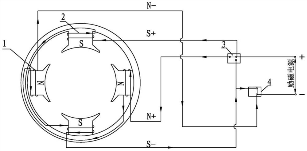
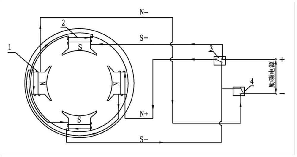
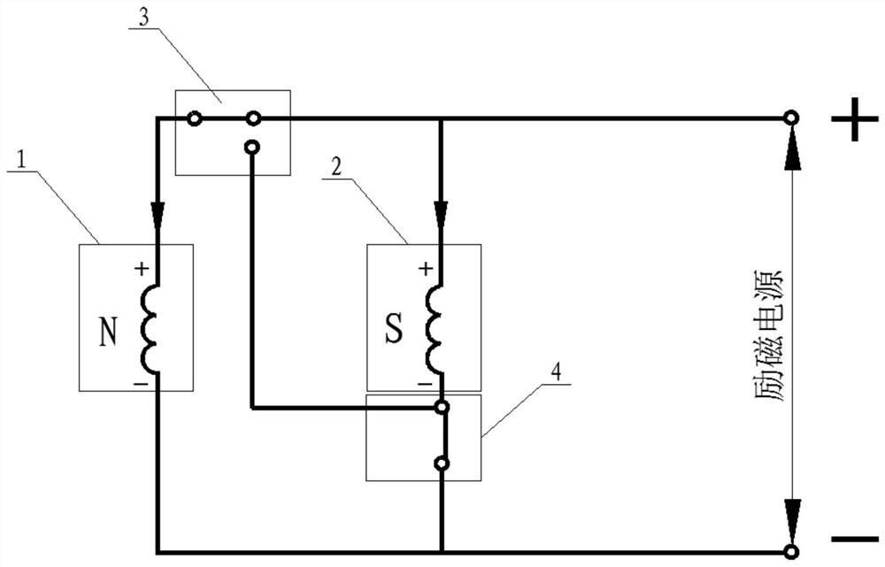
[0029] In this embodiment, a field winding and its starting / generating switching method that can change the winding series-parallel structure are proposed, so that the number of effective series turns of the exciting field winding of the exciter is reduced during starting, and the output capacity of the exciter is improved during starting. The number of effective series turns of the excitation winding of the exciter increases, so that the resistance of the excitation winding of the exciter increases, the excitation current decreases, and the excitation voltage increases.

[0030] The exciter excitation winding structure of the brushless electric excitation starter generator includes an N pole winding 1 and an S pole winding 2 , a first contactor 3 and a second ...


PUM


Abstract

The invention provides excitation winding structure of an exciter of a brushless electro-magnetic starter generator, and a starting / power generation switching method thereof. The winding structure comprises an N-pole winding, an S-pole winding, a first contactor and a second contactor. The N-pole winding is wound on the spaced magnetic pole iron cores in the exciter in series, and the S-pole winding is wound on the remaining spaced magnetic pole iron cores in series; one end of one winding is connected with the static contact of the first contactor, and the other end is connected with one contact of the second contactor and one pole of the excitation power supply; one end of the other winding is connected to one movable contact of the first contactor and the other pole of the excitation power supply, and the other end is connected to the other movable contact of the first contactor and the other contact of the second contactor; and the polarities of the two windings connected to the second contactor are the same. By changing the series-parallel connection structure of the windings, the number of effective series connection turns of the windings during starting is reduced, the output capacity of the exciter during starting is improved, and the number of effective series connection turns of the winding during power generation is increased, the winding resistance is increased, the excitation current is reduced, and the excitation voltage is increased.

Description

technical field [0001] The invention belongs to the field of brushless electric excitation starter generators, and relates to an exciter excitation winding structure and a starting / generating switching method thereof. Background technique [0002] In the starting phase of the brushless electric excitation starter generator, the exciter is equivalent to a transformer. [0003] In the existing brushless electric excitation synchronous starter generator, in order to increase the excitation current output by the exciter as the main generator armature, the number of turns of the excitation winding of the exciter is designed to be small, so as to increase the transformation ratio between the rotor and the stator winding of the exciter, so that Under the condition that the voltage applied to the excitation winding of the exciter remains unchanged, the output voltage of the exciter rotor increases, and the excitation current output by the exciter to the main generator increases. Un...

Claims


Application Information

Patent Timeline
IPC IPC(8): H02K1/14H02K3/28H02P9/08
CPCH02K1/14H02K3/28H02P9/08
Inventor 李丹姜宇管毅姚勋赵鹏
Owner SHAANXI AVIATION ELECTRICAL
Learn More