
Flow guide hole protection device

A protection device and a diversion hole technology, applied in the field of oil and gas well drilling, can solve the problems such as the failure of normal opening of the sliding sleeve, the solidification of the diversion hole cement, the influence of the reconstruction process and the reconstruction effect, etc.

Active Publication Date: 2021-08-31
CHINA PETROLEUM & CHEM CORP +1
View PDF8 Cites 0 Cited by
  • Summary
  • Abstract
  • Description
  • Claims
  • Application Information

AI Technical Summary

Problems solved by technology

However, during the running of the sliding sleeve, the diversion hole is easy to scrape with the well wall rock, causing wellbore mud and cuttings to easily enter the diversion hole. At the same time, cement slurry enters the diversion hole during the cementing process, resulting in the diversion hole being blocked. The cement solidifies, eventually causing the sliding sleeve to fail to open normally
The conventional method is to smear a layer of high-viscosity liquid on the diversion hole. During the lowering process and the circulation process, the high-viscosity liquid will eventually fall off and lose protection, resulting in the failure of the sliding sleeve to open normally, affecting the entire transformation process and transformation Effect

Method used


Image

  • Flow guide hole protection device
  • Flow guide hole protection device
  • Flow guide hole protection device

Examples


Embodiment Construction

[0032] The present invention will be further described in detail below in conjunction with the accompanying drawings and specific embodiments, but the protection scope of the present invention is not limited thereby.

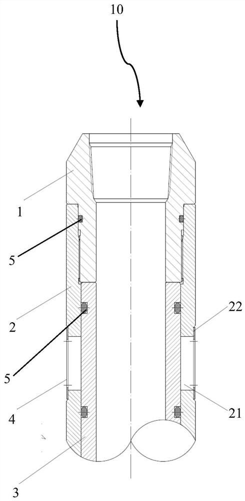
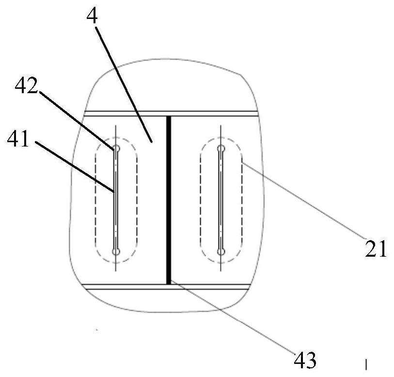
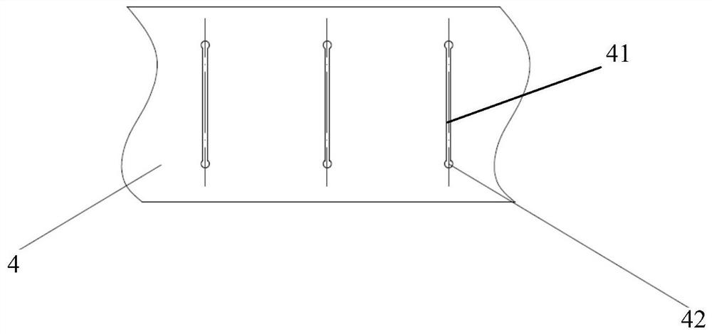
[0033] figure 1 The overall structure of the diversion hole protection device 10 according to the embodiment of the present invention is schematically shown. figure 2 A partial structure of the diversion hole protection device 10 according to the embodiment of the present invention is schematically shown. image 3 Another partial structure of the diversion hole protection device 10 according to the embodiment of the present invention is schematically shown.

[0034] like figure 1 As shown, the diversion hole protection device 10 of the embodiment of the present invention includes an upper joint 1 , an outer cylinder 2 and an inner cylinder 3 . Wherein, the outer cylinder 2 is sheathed on the inner cylinder 3 , and the upper joint 1 is connected with one end ...


PUM


Abstract

The invention provides a flow guide hole protection device. The flow guide hole protection device comprises an upper connector, an outer barrel and an inner barrel, wherein the outer barrel is arranged on the inner barrel in a sleeving manner; the upper connector is connected with one end of the outer barrel; flow guide holes which are uniformly distributed along the peripheral direction are formed in the outer barrel; protection sleeves sleeve positions corresponding to the flow guide holes; and the outer diameter of each protection sleeve is not greater than that of the outer barrel. According to the flow guide hole protection device provided by the invention, high-viscosity liquid in the holes can be effectively prevented from falling off and the flow guide holes are fully occupied by the high-viscosity liquid, so that external mud and cement paste are prevented from entering; and meanwhile, impurities including external rock debris and the like are also prevented from entering the flow guide holes.

Description

technical field [0001] The invention belongs to the technical field of oil and gas well drilling, and in particular relates to a diversion hole protection device. Background technique [0002] As the development of oil and gas reservoirs advances towards low-permeability and tight reservoirs, the wells are getting deeper, the reservoirs are getting tighter, the horizontal sections are getting longer, and the drilling and completion costs are getting higher and higher. In order to save the cost of well construction, open hole completion and casing sliding sleeve completion methods are generally adopted. However, during the running of the sliding sleeve, the diversion hole is easy to scrape with the well wall rock, causing wellbore mud and cuttings to easily enter the diversion hole. At the same time, cement slurry enters the diversion hole during the cementing process, resulting in the diversion hole being blocked The cement solidifies, and eventually the sliding sleeve cann...

Claims


Application Information

Patent Timeline
IPC IPC(8): E21B34/06E21B41/00
CPCE21B34/06E21B41/0021
Inventor 雷炜侯治民胡顺渠王强赵伟胡丹滕汶江刘涛陈晨钱江崔警宇
Owner CHINA PETROLEUM & CHEM CORP
Learn More