A tooling fixture and its clamping method

A tooling fixture, No. 1 technology, applied in the field of tooling fixtures, can solve problems such as increasing the workload of staff, and achieve the effects of preventing workpiece deformation or wear, reducing operating steps, and preventing dilution of cutting fluid

Active Publication Date: 2022-07-15
摩西智能工业股份有限公司
View PDF6 Cites 0 Cited by
  • Summary
  • Abstract
  • Description
  • Claims
  • Application Information

AI Technical Summary

Problems solved by technology

[0003] For the cylindrical workpiece, if it is to be processed in the machining center, the fixing method is generally to use an electromagnetic suction plate or a splint. If this kind of fixing method is used, the X and Y of the workpiece must be set after each workpiece is replaced. The zero point of the axis, which increases the workload of the staff, and the machining center generally processes high-precision parts. After the roughing of the workpiece, the staff usually needs to measure the size, which makes the staff often contact with the cutting fluid, which will give Staff present certain health risks

Method used


Image

  • A tooling fixture and its clamping method
  • A tooling fixture and its clamping method
  • A tooling fixture and its clamping method

Examples


Embodiment Construction

[0029] In the description of the present invention, it should be noted that the orientations or positional relationships indicated by the terms "upper", "lower", "inner", "outer", "top / bottom", etc. are based on the orientations shown in the accompanying drawings Or the positional relationship is only for the convenience of describing the present invention and simplifying the description, rather than indicating or implying that the indicated device or element must have a specific orientation, be constructed and operated in a specific orientation, and therefore should not be construed as a limitation of the present invention. Furthermore, the terms "first" and "second" are used for descriptive purposes only and should not be construed to indicate or imply relative importance.

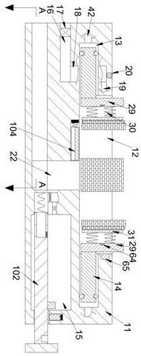
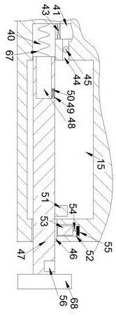
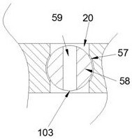
[0030] refer to Figure 1-7 , a fixture according to an embodiment of the present invention includes a fixing plate 11, and the fixing plate 11 is provided with a No. 1 cavity 12 with an upward opening a...


PUM


Abstract

The invention discloses a tooling fixture and a clamping method thereof, comprising a fixing plate, wherein a No. 1 cavity with an upward opening and a columnar shape is arranged in the fixing plate, with the axis of the No. 1 cavity as the center, the There are four hydraulic grooves at equal angles in the annular surface of the No. 1 cavity, and hydraulic rods are slidably connected in the hydraulic grooves. The present invention can clamp cylindrical workpieces and rectangular workpieces, and the invention can make the center of the workpiece Fixing, reducing the operation steps of setting the X-axis and Y-axis zero points before processing; and the invention can set the clamping force of the clamping, which not only prevents the workpiece from being deformed or worn due to excessive clamping force, but also prevents excessive clamping force. Small size may lead to poor machining accuracy; after the machining is completed, the present invention can clean the machining surface of the workpiece, prevent workers from contacting cutting fluid when measuring, and the cleaning water will be discharged to prevent the cleaning water from diluting the cutting fluid.

Description

technical field [0001] The invention relates to the technical field of tooling fixtures, in particular to a tooling fixture and a clamping method thereof. Background technique [0002] The fixture refers to the device used to clamp the workpiece, which can fix the workpiece to be processed on the machine tool and make it easy to process. [0003] For a cylindrical workpiece, if it is to be processed in the machining center, the fixing method is generally to use an electromagnetic suction plate or a splint. If such a fixing method is used, X and Y must be set on the workpiece every time the workpiece is replaced. The zero point of the axis increases the workload of the staff, and the machining center generally processes high-precision parts. After the roughing of the workpiece is completed, the staff usually needs to measure the size, which makes the staff often contact the cutting fluid, which will give Workers pose certain health risks. SUMMARY OF THE INVENTION [0004]...

Claims


Application Information

Patent Timeline
Patent Type & Authority Patents(China)
IPC IPC(8): B23Q3/08B23Q11/00B23Q11/10
CPCB23Q3/08B23Q3/082B23Q11/10B23Q11/0042
Inventor 郭彩
Owner 摩西智能工业股份有限公司
Why Eureka
Try Eureka